|
|
Post by peterberg on Apr 27, 2019 8:07:53 GMT -8
2.9.1.0 Thank you for this clarification, it is great and super clear! My problem arose with the version of DSR2 RC1v8.skp I got. I have been busy with editing drawings and shifting features, and running short tests to see what the effects were. It turned out that with just small amendments it became very easy to scale the thing and explain to someone how it could be done. At the same time, that's what you get with a first release candidate, changes in small details are to be expected. |
|
mac84
New Member

Posts: 5
|
Post by mac84 on Apr 29, 2019 12:41:47 GMT -8
Peter, Fantastic work on this project and the many others before. I have a quick question if you do not mind.
Do you think there needs to be a step where the back wall of the riser meets the top box? From the pictures on the first page there seems to be just a small step. It doesn't match the "first candidate" sketchup model. Could the design be simpler without the step?
|
|
|
|
Post by peterberg on May 1, 2019 2:15:42 GMT -8
Do you think there needs to be a step where the back wall of the riser meets the top box? From the pictures on the first page there seems to be just a small step. It doesn't match the "first candidate" sketchup model. Could the design be simpler without the step? Good question. The small step you referring to is 15 mm, due to space restrictions it couldn't be more. During every burn the view shows the flames are flaring out left and right. Sometimes it's also visably, not easy to see, flaring out to the rear. So I'm inclined to think this step would better be there. The RC1 drawing shows a step of 30 mm, the same as left and right. Filling in the steps left, right and rear seems to be logical, it can be done using the same material. Having said that, I didn't start with the hard refractory reference design, yet. I'll build some possibilities in there for trying out other simplifying features. Too early to publish in detail because it's just a brainwave, nothing else. |
|
|
|
Post by peterberg on May 17, 2019 11:47:14 GMT -8
|
|
|
|
Post by wiscojames on May 17, 2019 18:36:19 GMT -8
Yes! Love seeing where this development has gone. The build is becoming simpler (as long as one can access the right materials), and the aesthetics are improving as well, with a better view of the fire. Well done, Peter.
|
|
|
|
Post by josephcrawley on May 18, 2019 5:26:02 GMT -8
Peter did you get rid of the stumbling block?
|
|
|
|
Post by sksshel on May 18, 2019 7:09:28 GMT -8
Can the firebox be constructed 100mm longer? If so, where would the extra length be added to the top shoebox?
|
|
|
|
Post by peterberg on May 18, 2019 9:44:14 GMT -8
Peter did you get rid of the stumbling block? No, I didn't. It's still there, being the last change after the smaller end port. All the excellent results are achieved with this in place so I'd intend to keep it. |
|
|
|
Post by peterberg on May 18, 2019 9:52:44 GMT -8
Can the firebox be constructed 100mm longer? If so, where would the extra length be added to the top shoebox? I'd think the firebox could be longer, yes. But you could also scale up from the last drawing. I did, it's scaled up from 120 mm to 125 mm system size. Not much, but it turned out to be a better fit with the available materials and barrels. Regarding the top box, I'm inclined to think the same proportions would be best. So, stumbling block centered halfway in the depth of the box, exhaust port halfway in the remaining space. That is to say, if you want the top box to be accessable as an oven or for fun. Otherwise the top box could be the same length as before the extension. |
|
|
|
Post by peterberg on May 18, 2019 10:03:44 GMT -8
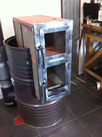
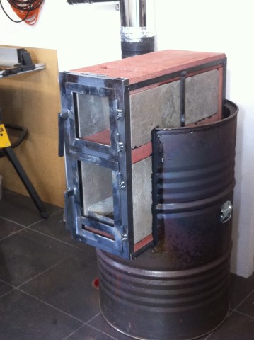
Making good progress today, doors are done. Complete with hinges and closure handles. There are some things left to do though. A valve for the combined air inlet, fittings for the glass and spray painting with heat resistant paint.   My intention is to do testing with two different floor channels. Both need to be cut down to length in order to fit behind the combined air inlet. There are more possibilities to figure out, I'll publish progress while I go along. Interesting times! |
|
|
|
Post by independentenergy on May 18, 2019 23:28:49 GMT -8
Very interesting Peter.
Did you use superwool in the first part of the conduit for convenience or for technical reasons?
|
|
|
|
Post by peterberg on May 19, 2019 0:54:00 GMT -8
Did you use superwool in the first part of the conduit for convenience or for technical reasons? From a technical point of view it's beneficial to have a highly insulative afterburner. Earlier up to operating temperature while the rest of the structure is just hard firebrick or in my case, refractory concrete slabs. The top box could be used as a real oven because of this. For convenience, yes, it's very quickly done. In mere minutes the riser stub was down to the calculated square 125(ish) mm. At first, I planned to use some of the ceramic fibre board but since it's thicknes is twice as much as required I needed to make it thinner with a hacksaw. Very messy, very inconvenient... |
|
|
|
Post by independentenergy on May 19, 2019 2:08:44 GMT -8
I'm puzzled, in case you were to use it as an oven, ceramic particles could be deposited on the food in direct cooking.
What do you think? could you use other material?
for example thin refractory slabs insulated on the outside.
|
|
|
|
Post by peterberg on May 19, 2019 5:35:08 GMT -8
There are kinds of refractory concrete that are quite insulating, using that would eliminate ceramic particles. Or thin insulating firebricks would be an option as well. The quality of those bricks I used here was very poor, all the bricks in the top box were breaking up when I took it apart. So I couldn't use that bricks again but given better quality this would be my first choice.
And ultimately, direct cooking in my oven would be done in proper cooking vessels with lid. One exeption would be pizza, for that one would need a bigger size core without soft ceramic fibre, say 8" would be quite doable. Calculating... 45 cm wide, sounds quite sizeable to me.
|
|
|
|
Post by independentenergy on May 19, 2019 10:00:14 GMT -8
for me the problem is to find the insulating bricks, generally they do not exist flame resistant, they are to be installed behind the refractories.
Even if lately some companies have produced insulating castable refractories that could be the solution.
I thought about the use of vermiculite boards also if they do not have the thermal characteristics to withstand certain temperatures since they have no bearing function they could work ?
The pizza in a high temperature oven would be ideal, I was thinking of a 150mm system that is certainly not the most suitable but taking advantage of the length you can also use it for pizza I think.
|
|