|
|
Post by breckwoldt on Aug 26, 2019 3:30:06 GMT -8
I see, all the bends and turns gives a lot of friction in the chimney. Since everyones install has slightly different requirements and circumstances getting a firm grasp of the many dynamic factors at play seems most valuable. -Thanks!
|
|
gyula
New Member

Posts: 2
|
Post by gyula on Mar 27, 2020 10:06:09 GMT -8
A question regarding air tightness of the heater, please.
It looks like the top common brick row does not attach to the sides of the bell with mortar:
The space between them is not sealed - it is rather filled with ceramic blanket.
It can be seen in the video at 3:28.
Similarly, the joints of the bench top is filled only with blanket - at least in case of the first row (seen at 3:16).
Can such mortar-less joints allow smoke or carbon monoxide to escape into the room?
Thanks for sharing!
- Gyula
|
|
|
|
Post by peterberg on Mar 27, 2020 11:56:50 GMT -8
Maybe you are missing some details, I'd say. In fact, it's dangerous to seal joints between hotter and cooler parts with mortar. The superwool is providing a flexible joint in contrast with rigid mortar which could (and believe me, it will!) crack because of expansion.
Moreover, in the bell's top the sealing with superwool is tripled in three consequetive layers. Superwool on it's own, pressed together, is a quite effective way to seal.
As for the bench: the joints in the first layer are done with superwool where there's no brick underneath. At the back and front, where there are bricks underneath it's done with mortar. Reason for this is simple: having mortar in such a joint means it could fall out over time, the superwool is glued in place. The second layer is all done with mortar with overlapping joints. This is different from the bell's top, the reason for this is the much lower temperature in the bench so the expanding and contracting of the bricks doesn't exist there.
And last but not least: the inside of such a heater, while running properly, is all in under pressure. So air is sucked in through leaks that could exist, no CO is blown out. I've done a huge number of tests while the Testo analizer sports a build-in sensor for CO in the room. It never gave as much as a beep.
|
|
|
|
Post by moritz on Dec 13, 2020 2:54:23 GMT -8
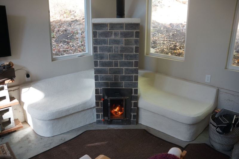
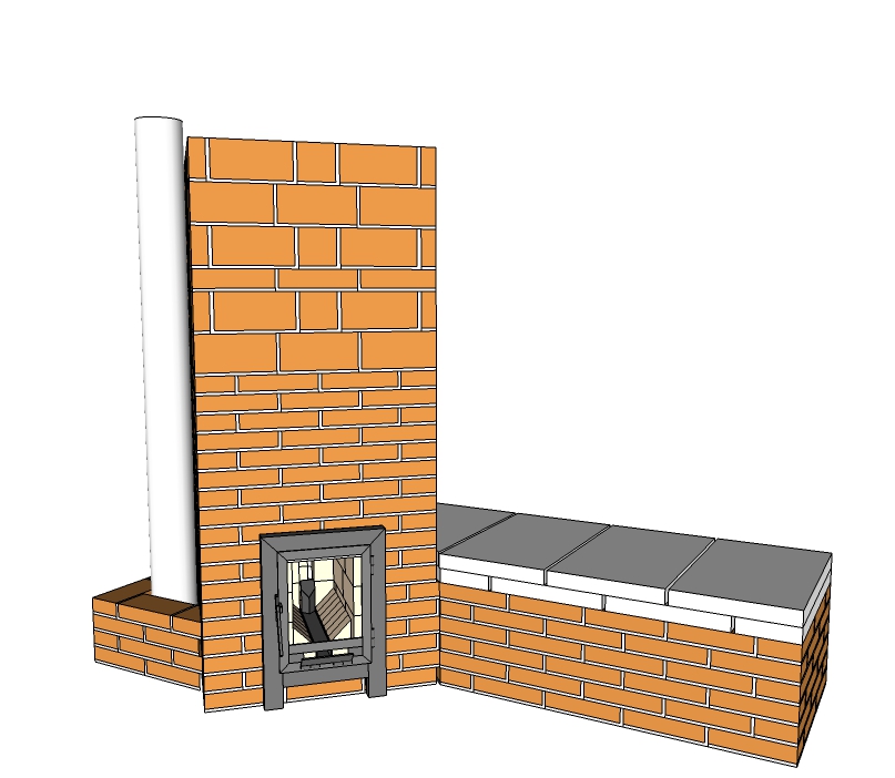
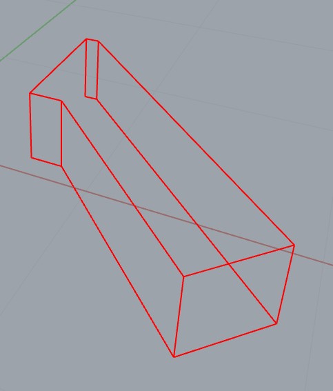
As is probably clear, I used an idea first employed by Donkey for his double bench heater which is strictly symmetrical.  Luke and Tracy's heater is asymmetrical in that there's just a bench at one side and the exhaust funnel at the other. It's also a 6" system but the main bell and the bench are much wider inside so the ISA is 5.2 m² for this heater, not counting the floor and the firebox. It's deliberately slightly underspecced so the thing would be able to start without any problems in almost all circumstances. The 45º angle of the main bell to the bench makes the opening between those very wide, so there's a pillar in the middle of the bridging in addition to twin steel bars. Those spaciously openings to the bench and the exhaust are responsible for the very, very low friction in the system. Which in turn made it possible to light the first fire without any precautions like priming the chimney. We left the air inlet open during the night and Luke started the thing again the next day, probably just before noon. As he reported, without a hiccup at all despite the fact the heater was cooled off nearly completely and still very wet. Today I amended the drawing to the state it was actually built, the SketchUp file can be downloaded via this link. The file is in SketchUp version 8.  Good morning. I just downladed the sketchup file and measured the ISA of this build with my CAD Software. I am getting a result of 5.62m² total ISA.
3.83m² for the bell and 1.79m² for the bench,  . not counting the floor and the firebox. You say though "deliberately slightly underspecced". But 5.3 is the maximum ISA on batchrocket.eu. I am wondering if I am missing out on something. Best. Moritz
|
|
|
|
Post by peterberg on Dec 13, 2020 3:30:07 GMT -8
What I did is this: I used SketchUp itself to do the calculations by making an area over each inner surface and selecting all those. In your calculation there's only one side open to the bench but in reality the other side is also open. Furthermore, the surface area where the firebox is situated doesn't count as well. Together, could well be the discrepancy of 0.4 m². Are you sure the internal height of the bell is correct?
|
|
|
|
Post by moritz on Dec 13, 2020 6:09:49 GMT -8
What I did is this: I used SketchUp itself to do the calculations by making an area over each inner surface and selecting all those. In your calculation there's only one side open to the bench but in reality the other side is also open. Furthermore, the surface area where the firebox is situated doesn't count as well. Together, could well be the discrepancy of 0.4 m². Are you sure the internal height of the bell is correct? Hi Peter. Thats exactly what I did. I constructed a surface over the interior Surface of the bell (floor excluded) and measure that..

I now removed another square in front, where the fire box sits and the opening towards the chimney. My CAD says now 5.43m². But anyhow. I guess its very close to the realm of 5.3m² You intended slightly under sized, I measure slightly oversized in the CAD.
Why are my images not showing and only remain a s a link?
|
|
|
|
Post by peterberg on Dec 13, 2020 7:38:09 GMT -8
Why are my images not showing and only remain as a link? Your images are on a http: link instead of https:, this forum only accepts the latter for showing directly. Some time ago I experienced the same problem, all the pictures being on my website didn't show up anymore so I opened a new website and changed all the relevant links. I am the one who added the links to your pictures myself, being a moderator. see the Last Edit notice at the bottom right corner of your post. |
|
|
|
Post by moritz on Dec 13, 2020 7:52:03 GMT -8
Why are my images not showing and only remain as a link? Your images are on a http: link instead of https:, this forum only accepts the latter for showing directly. Some time ago I experienced the same problem, all the pictures being on my website didn't show up anymore so I opened a new website and changed all the relevant links. I am the one who added the links to your pictures myself, being a moderator. see the Last Edit notice at the bottom right corner of your post.
Oh. Thanks for adding the links. Now I've got to figure out how I get a https webspace...
|
|
|
|
Post by willowman on Jan 15, 2023 8:54:28 GMT -8
Hello all,
Myself and another stove enthusiast are working together to build a batchrocket bell in our two respective houses based on this Mallorca build. He, a 7" with a bench, me a 6" bell only. We live in Northamptonshire, UK. We are building the 7" stove with bench first and have a few questions:- The Sketchup plan shows that the core 'foundation' protrudes beyond the rear of the core and the house brick core foundation is wider than the core. Is this necessary for the reason of stability? There is a link to download a drawing of the core towards the bottom of the 'Designs' page of batchrocket.eu, immediately under the timelapse video. This is somewhat different to the core design on the latest Sketchup plan. Can we ignore the drawing of the core? How does the door assembly attach to the masonry? Is it screwed through the six tabs that protrude the back of the door assembly? Are the remaining metal parts welded/slotted into place? And finally, are 25mm ('split') firebricks substantial enough to line the bell above the riser? I ask because UK bricks are 100mm wide as opposed to the 120mm wide bricks used in Mallorca?
Thank you for any replies.
|
|
|
|
Post by peterberg on Jan 17, 2023 2:59:28 GMT -8
We are building the 7" stove with bench first and have a few questions:- The Sketchup plan shows that the core 'foundation' protrudes beyond the rear of the core and the house brick core foundation is wider than the core. Is this necessary for the reason of stability? No, it isn't. The normal red bricks were too big and should be cut smaller but we choose not to. There was lots of space around it, that's all. There is a link to download a drawing of the core towards the bottom of the 'Designs' page of batchrocket.eu, immediately under the timelapse video. This is somewhat different to the core design on the latest Sketchup plan. Can we ignore the drawing of the core? The core of the Mallorca build turned out to be a little bit smaller, I'd think that's what you mean. This slightly downscaling was done because the available refractory bricks were somewhat smaller than usual. Please ignore the drawing and stick to the calculated values. How does the door assembly attach to the masonry? Is it screwed through the six tabs that protrude the back of the door assembly? Are the remaining metal parts welded/slotted into place? The six tabs at the back of the door frame are used to fix the door assembly to the core by means of three steel wires, all around the core. The door frame won't slip down because it's resting on the floor with its two short legs. This could be done differently, two strips left and right of the frame and fixed with screws to the bricks of the bell, not the core. And finally, are 25mm ('split') firebricks substantial enough to line the bell above the riser? I ask because UK bricks are 100mm wide as opposed to the 120mm wide bricks used in Mallorca? Yes, split firebricks will do. Another approach would be like the Brussels build, One layer of bricks are at right angles with the bricks underneath, thus creating space for the liner bricks on the inside. Those red bricks were only 188x88x63 mm so there wasn't enough space to do it otherwise. Keep in mind, it would be best to center the turned bricks above the others. |
|
|
|
Post by willowman on Jan 17, 2023 9:38:54 GMT -8
Thank you Peter.
For the housebrick courses above the riser we plan to use a housebrick split along it's length which will take up approx 50mm of the width. Inside this will be insulation and the split firebrick.
|
|
|
|
Post by willowman on Mar 18, 2023 10:06:44 GMT -8
Hello again,
We are beginning to build the core of the 7" stove. I have some questions about the floor channel. We are building as per the 2019 update on the Designs page of batchrocket.eu which shows the "larger feed part and a higher stub"
Would you make the dimensions for our 7" stove correspondingly larger than those for the 150mm feed part? I presume the answer is Yes. If so, also increased dimensions for the stub?
The floor channel seems to 'hover' 10 mm above the surface beneath. I am sure there is an obvious explanation from sketchup but I am not seeing it. Would you please explain?
|
|
|
|
Post by peterberg on Mar 21, 2023 1:30:46 GMT -8
Feed and stub parts should be scaled up alike the rest of the heater. Let's see... the stub size for a 150 mm system is 35x35x2 mm, a 180 mm (roughly 7") system calls for a stub of 20% larger internal csa. Which is 37.958799 mm square, wall thickness of the stub 2 mm. This is very impractical, I would go for a 40x40 mm stub, wall thickness 2 or 3 mm and Bob's your uncle. So two square ducts side by side of the same size is what I would use for the feed.
It took a while what you meant with the second question, but I get it now. The drawing reflects the true build as close as possible. The steel parts where made in Mallorca by a local craftsman, according to my specs. So the steel feed of the floor channel is 40 mm thick, the refractory bricks left and right 50 mm. In order not to compromise the height of the stub compared to the port height we placed two 10 mm fill blocks under the feed.
There are more ways to solve this, of course. Making the stub 10 mm higher is one of those and accept an extra layer of 10 mm ash on the feed. But incorporating this in the drawing bears the risk that a clever individual would find out the discrepancy between the drawing of the single floor channel on the website and the drawing of the Mallorca build. So it's up to you which solution to incorporate in your build, both would work well.
|
|
|
|
Post by willowman on Mar 23, 2023 9:19:47 GMT -8
Thanks for your reply Peter.
Apologies for appearing stupid. I understand the stub for the 180mm will be made from 40x40mm. The feed (horizontal floor channel) of the 2019 update is 65mm wide and 40mm high. Scaling this up for our 180mm stove could be a new width of 75mm with the same height of 40mm. I calculate the csa of the 2019 update to be 2016 sq mm. A csa of 75mm wide, same height, would be 2376 sq mm which is very close to a 20% increase.
Therefore, would you agree, the feed for our 180mm stove is to be made from 75x40mm and the stub from 40x40mm as you advised.
|
|
|
|
Post by peterberg on Mar 24, 2023 2:37:04 GMT -8
I'd think there's a glitch: the horizontal feed for a 150 mm system is 60x40x2 mm according to the drawing, although your calculation is correct for a duct size as above.
As you may know, there are common available duct sizes in millimeters and 75x40x2 mm isn't one of those. Once you've found the correct stub size, it's much easier to use this same duct side by side for the feed. Fabricating it can be done with a thin cutting disk grinder and stick welder only. I've done it a couple of times, both a double square duct and a single rectangle duct, in my opinion the former is easier.
By the way, 80x40x2 mm is a standard size, as is 80x40x3 mm, both within specs. But a 75x40x2 mm duct will do as well provided you are able to find it.
Succes!
|
|