|
|
Post by peterberg on Oct 12, 2011 6:14:04 GMT -8
As I've written a couple of days ago, the main target has been to reduce the spiky behavior. The new setup has done just that, at a cost. The best performance is reached with small and uniform fuel. I've been using soft wood, pieces of about one foot long and less than one inch wide and thick. Because of the short pieces, constant attention is needed to keep the fire going at its highest level. That is to say, with this small 4"x4" incarnation. Of course when testing an up scaled item the fuel can be scaled up as well. The use of a cast refractory burn tunnel resulted in longer warming-up times. In sharp contrast with the heat riser, which can be awfully hot in mere minutes. The best way to illustrate that is one of the better graphics produced by one of the all-steel versions. 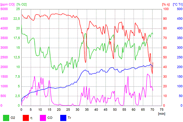 From the start of the burn, it'll cost about 20 minutes to reach the higher temperatures during which more or less complete combustion can be reached. The purple line of the CO level at that point will come very low and it'll stay there for as long as 10 to 20 minutes. After that another border is reached and the CO goes up again in short spikes, as clearly shown by the graphic. The new version do behave differently, heating up time is twice as long. Sometimes there has been an occasional spike, and somewhere around 70 to 80 minutes the other border is reached. Averages for this testrun is very, very good, in fact about a factor two better if compared to the average steel version. O2 10.5 %, eff 90.3 %, CO 304 ppm, end temp 289 F. 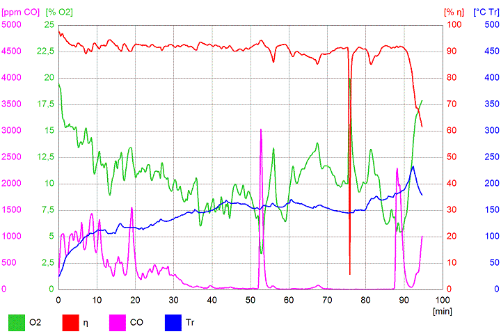 The dip in the red efficiency line is caused by filter changing of the Testo without interrupting the testrun. As a result of this run, I've concluded the 2nd air stream was slightly too small so I've altered the opening in the refractory base to solve that. The main question is now: are these commendable results triggered by which change? I don't have any real proof at hand to answer that, only an educated guess. From the top of the upper barrel I could look into the heat riser, and down there wasn't any sign of the curved back end of the burn tunnel really made a difference. Most of the time the flames came straight out of the tunnel. During a couple of testruns I was able to make a short film of that. Nothing different from the earlier videos I've made. So I've concluded: the back end of the burn tunnel could be a simple ramp, to prevent the ashes to accumulate there. The tile roof shape of the tunnel ceiling and the trip wire remain to be evaluated. My guess is, the trip wire is of the utmost importance to disrupt the boundary layer at the ceiling. The difference between former versions and this is so great and consistently, random results are virtually impossible. All the tests where performed with a duration of 100 minutes or less. But a rocket mass heater is a system that can be fired for as long as 6 hours. So I've planned a 3 hours duration test to see whether there would be other surprises down the time line. To be fair, I've done my very best to provoke the thing by making the 2nd air stream opening smaller and wider again, and frequently pushing the fuel into the feed tube. 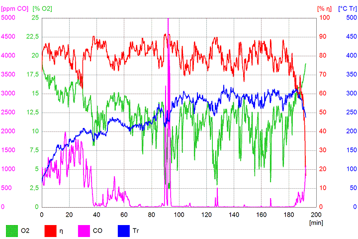 The CO line is constantly moving for 40 minutes, between 2000 and 500 ppm. After that it'd only move between 0 and 800 ppm. I've let it ran up to 90 minutes with the 2nd air opening half open, just to try and find the smallest opening. After that big spike I've opened it for three quarters. All the downward green spikes are caused by pushing the fuel in as far as I could. The sound of the thing was as purring like a friendly but giant cat, except during the pushing actions. Then the noise went up to a loud and aggressive roar for one minute or less, the barrels began to rattle and my wife came down to ask what was going wrong. These results are extremely good, averages are O2 12 %, eff 79.4 %, CO 312 ppm, end temp 468 F. The filter of the Testo analyzer, used during that three hours had a light grey colour instead of all the variants of black which is normal for wood burning. Efficiency could be higher, simply by placing another barrel on top or building a bench, adding a bell or whatever. But I've done these tests to find out what triggered the best combustion. The kind of noise was like a V1 pulse jet engine. Exactly like 15 seconds into the video down here, probably not as loud. ;D At the same time the fuel was eaten away at a racing pace, which is why it didn't last longer than a minute. Looking into the top of the barrel I was able to see a 3 foot heat riser full of fire, like a fountain shot up into the top barrel and curling down before reaching the lid. To my regret, I couldn't make a video of that phenomenon, by lifting the plug it killed the effect in a mere 4 seconds. Besides that, the temperature of the top barrel went up to 600 F. 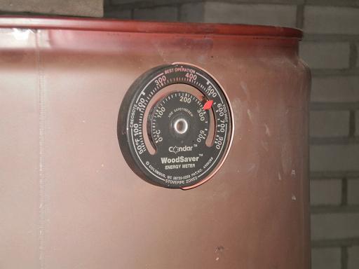 I'm not sure what phenomenon I've been watching. The immensely roar suggest a pulse-jet effect, but there are no valves in the rocket so where on earth is that noise coming from? The answer lies in my opnion in another rocketish apparatus, a valveless pulse jet. This consist of a tube which is the jet itself and a smaller diameter bended piece, together forming... a J-tube! Try googling "valveless pulse jet" when you are interested. |
|
|
|
Post by stovol on Oct 12, 2011 13:42:48 GMT -8
awesome data peter! do you have the ability to zoom in on the trip wire set up... ? i'm trying to learn google sketchup now to make a 3d model of what i intend... do you think a zig zag shaped protrusion along all four walls of the burn tunnel near the riser would be something to try as a turbulator? i assume the one on the roof would be the most important... i'm worried about proportion and causing a restriction though.. once it is cast thats it!
|
|
|
|
Post by peterberg on Oct 13, 2011 0:51:14 GMT -8
do you have the ability to zoom in on the trip wire set up...? Looking through the pictures, I could only find the originals, so I've made a cut-out of two. As you can see, the ridge itself is quite small, 5.5 mm or about 0.2" in my set up. Even in a larger system it doesn't need to be much larger, say 7 mm in a 6" system. The pictures are seen in direction of the stream. The ridge do start at both walls 1,5" from the feed, angle 30 degrees (not critical), pointing to the riser. 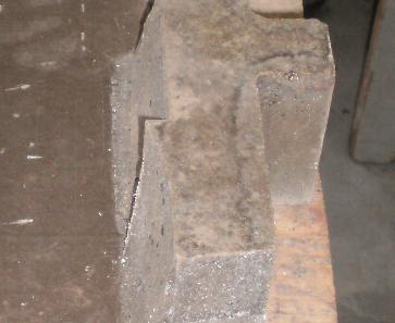 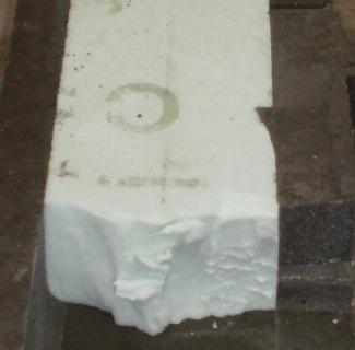 do you think a zig zag shaped protrusion along all four walls of the burn tunnel near the riser would be something to try as a turbulator? The trip wire at the tunnel floor is really a waste of time, ashes could be deposited there. At he walls maybe it could work, I would say the upper half is your best bet. Start the ridge at the same point as the ceiling and extend it to the floor, fading out on the way. Also with the same angle as the top one. No zig-zagging, please don't make it too large or with multiple wires, it won't help to disrupt an already disrupted stream. Remember the cap of those world cup skaters? It is a single strip, only 2 mm high, it is zig-zagging only because maintaining an angle to the stream gives better effect. As an aside for the refractory castable: you need a vibrating table of some sort. See this one for the simplest one, the vibrating motor could be replaced by a power drill mounted to the plywood board. In the drill an excenter, and you have your vibrating table. Please be very frugal with the water, try to keep the mix as dry as possible. And last but not least: vibrating longer with low power will give better results. Best of luck! |
|
|
|
Post by stovol on Oct 13, 2011 14:55:56 GMT -8
thanks bro, that vibrating table is killer! i'll have to try one of those for sure...... if i dont vibrate the casting, will it screw it up? remember, mine will be a thin shell... inch thick at most.. with 1inch 8lb density ceramic fiber blanket behind... prob with something like durock for tile as my outside shell
|
|
|
|
Post by peterberg on Oct 14, 2011 9:52:34 GMT -8
thanks bro, that vibrating table is killer! i'll have to try one of those for sure...... if i dont vibrate the casting, will it screw it up? I'm very sure it will be screwed up without the use of a vibrating table. More precise, it is possible to get the air out of the mixture with other means. The table is simply the best tool for that purpose, period. But don't use a vibrating needle, the wall thickness of the casting is too tiny for that. remember, mine will be a thin shell... inch thick at most.. with 1inch 8lb density ceramic fiber blanket behind... prob with something like durock for tile as my outside shell The casting I've done for the rocket has got the same thin shell. This is the lower limit which is still a workable solution. It is strong enough and I've seen it glowing red several times. Specification for this particular type I've been using is 1200 C, which equals 2190 F. |
|
|
|
Post by Donkey on Oct 17, 2011 19:29:53 GMT -8
Wow. Great work once again, Peter! Thank you SO much for sharing your data! What appears to be the ideal dimensions for your "secondary air" slots? Have they solved the metal burnout problem or would surrounding the feed entirely with some similar arrangement improve by cooling all 'round it? Your tripwire is VERY interesting.. Looks like I'll need to build myself a shake table sometime soon.  I know the sound that you've described.. I've heard it before, though for me it's mostly been a transient effect. Are you SURE that the shape of the back of the burn tunnel isn't causing what you're seeing, or is it still to early to tell yet? Thanks again! |
|
|
|
Post by peterberg on Oct 18, 2011 9:28:24 GMT -8
What appears to be the ideal dimensions for your "secondary air" slots? There happens to be only one slot. Dimensions depends heavily on the rest of the configuration. In the all-steel version 4" x 0.2", without cooling the top end of the feed tube. In that way, the air is coming in at a relatively low temperature. With the added benefit of the feed cooler, temperatures will be higher in that slot. In this situation the slot could be larger at the same time, about 4" x 0.4". All for a 4" x 4" system, of course. Have they solved the metal burnout problem or would surrounding the feed entirely with some similar arrangement improve by cooling all 'round it? No the burnout problem is still there, but the bottom of the feed tube is made of refractory now. And surrounded by insulation, only the top end of the feed is cooled. So, the bottom of the feed is red hot, the top end is cooled and creeping up of the fire is history, none of the six testruns showed any sign of that problem. I know the sound that you've described.. I've heard it before, though for me it's mostly been a transient effect. Are you SURE that the shape of the back of the burn tunnel isn't causing what you're seeing, or is it still to early to tell yet? The all-steel versions had the same effect just now and then, more or less at random. I'm not sure about what is causing it, my guess is: the temp is just high enough, caused by the 2nd air slot and the trip wire. Some of the precise details is a feed which is as full as possible, the fuel is gasifying at an enormous rate. Small and short inlet, large outlet, J-shape tube, all the conditions are there for a short-lived valveless jet engine. No sharp corners inside, at the back of the tunnel, is possibly another condition. |
|
|
|
Post by Donkey on Oct 18, 2011 10:25:28 GMT -8
I've noticed the issue you mentioned earlier, that when the fuel is up against the front of the feed, it doesn't run as efficiently. Unfortunately at the same time, when the fire starts creeping up the wood, often the solution has been (in the "classic rocket feed arrangement) to push the wood to the front and narrow the feed from the back with a brick. This solves (or reduces), for the moment, the fire creep issue at the expense of complete combustion.. What I like about your slot(s) is that it solves BOTH problems handily. I'm thinking about making a metal insert with tabs (for spacing and holding it up) to place inside the feed as a modification for stoves that have already been built. I imagine it would look something like this: 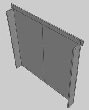 The tabs on the top would hang the thing on the bricks of the feed and the tabs on the sides would stand it off of the front and provide the air slot. Around here, I've built a LOT of 8 inch stoves, so I've got to scale up to that from the 4 inches that you are working with.. My initial, off the top of the head thought is that the slot should be around a half of an inch deep by the full 7 inches wide(minus the thickness of the metal).. Would you say that's fairly close, at least close enough to get started? Is there some general rule about proportions that would get me close (or exactly) to the right answer or is it just a try and see kind of operation? |
|
|
|
Post by peterberg on Oct 18, 2011 12:50:27 GMT -8
What I like about your slot(s) is that it solves BOTH problems handily. Yer right, my friend, provided the top end of the feed is metal, and cooled by the streaming air around it. That will keep the temperature below the self-combustion level of the wood. Around here, I've built a LOT of 8 inch stoves, so I've got to scale up to that from the 4 inches that you are working with.. My initial, off the top of the head thought is that the slot should be around a half of an inch deep by the full 7 inches wide(minus the thickness of the metal).. Good results were obtained (in my case) with a gap consisting of 5% to 9% of the total opening. That is to say, the 9% with the cooling facility, which had a wider gap. Somewhere between those two is 7%. The cross sectional area of an 8" system is 50 square inch. 50x7% equals 3.5 square inch, divided by the 7" width of the feed and you've got 0.5". Close enough to get started, I would say. Don't forget to let it hang the same 0.5" lower than the ceiling of the tunnel. By that way, you are creating a small vacuum behind the plate. And make the plate higher and wider above the feed, in order to create two different air streams. One through the fuel, the other through the 2nd air slot. A world of difference, according to the Testo. |
|
|
|
Post by Donkey on Oct 19, 2011 9:01:53 GMT -8
Good results were obtained (in my case) with a gap consisting of 5% to 9% of the total opening. That is to say, the 9% with the cooling facility, which had a wider gap. Somewhere between those two is 7%. The cross sectional area of an 8" system is 50 square inch. 50x7% equals 3.5 square inch, divided by the 7" width of the feed and you've got 0.5". Close enough to get started, I would say. Don't forget to let it hang the same 0.5" lower than the ceiling of the tunnel. By that way, you are creating a small vacuum behind the plate. And make the plate higher and wider above the feed, in order to create two different air streams. One through the fuel, the other through the 2nd air slot. A world of difference, according to the Testo. Yes!! Those are exactly the kinds of detail that make ALL the difference. Thank you again! |
|
|
|
Post by Donkey on Oct 19, 2011 12:43:20 GMT -8
OK, So I made one to fit the hot water heater in my bath house.. I had a piece of hot water heater tank left over from a different project, I cut off a chunk, hammered it flat and cut it out with a jigsaw. It's in the shape of a T, the wings on top stick are 3 inches wider (on both sides) than the feed opening and it projects 3 inches up from the top (all the way across). The bottom projects a half inch below the first brick and the sides bend forward to act as spacer and air channel. I've started with a 3/4(.75) of an inch air gap, I figure that it's easier to make it too big and grind down to the right size. In measuring my feed opening, I've remembered that I made it slightly narrow and long so that an arm can easily reach in for cleaning. The opening is 6.75 inches wide. I'll post an image when I find the camera (I think my kid took it to her photography class today). I placed the piece in the stove, lit it and fiddled a bit. It had a slow start problem, which is rare for this stove. I used a piece of cardboard to cover the channel and the stove picked up speed immediately. It ran noticeably faster with the air channel closed. While poking at it, I couldn't help but notice that I had cut the edges raggedly which made a clean measurement impossible as it wouldn't set flat on the bricks. So I pulled the piece out, doused it with water to cool it and ground the edges down clean, evening out the edges nicely. I placed the piece back in the stove, loaded it with a second load of wood and squatted to fiddle some more. Same result as before. The stove was definitely up to temperature by this point and it still ran better with the air gap closed. I held a lit cigarette over the fire-box and blew an even cloud of smoke at it.. The secondary stream draws aggressively and there appears to be no (or little) interference between the two. I think the air gap is too large, I'll grind it down 1/8 of an inch and try again.. Not today though, I've got a tank of quite hot water and will boil it if I add more fuel.. I guess I'm off to have a nice shower.  |
|
|
|
Post by peterberg on Oct 19, 2011 13:16:09 GMT -8
@donkey,
Yes, that 0.75" gap is far too large, but you've seen it working now. I've done the calculation again for the width of your feed with the 5% value, and this suggest a 0.37" gap should be adequate. So, the one you're using today is (probably) too large by a factor of 2!
May I suggest you use the same size for the gap and overhang? In case the draw is still too aggressively, reduce both measurements even further.
I am very curious!
|
|
|
|
Post by endrunner on Oct 21, 2011 11:14:35 GMT -8
I am sorry but I am not following the "trip wire" I get the gap on the feed tube, and curled combustion zone exit to the heat riser, but what is a "trip wire"?
BTW Always love and truly admire your work.
|
|
|
|
Post by Donkey on Oct 21, 2011 11:28:39 GMT -8
Yesterday, I tried another run.
First, I reduced the gap to .5 inch, in keeping with the idea of approaching the right gap size slowly.
At a half an inch, the slow start problem was reduced, though still present and once again, there was a definite improvement when the gap was covered (closed).
So I pulled out the piece, cooled it and ground it down to a 3/8 inch gap.
I returned the piece to the stove, stoked it up again with it's second load and watched it go.(a reminder that the stove was fully hot as it had burned through one full load) This time, there was no discernible difference when the gap was closed off. After trying several times to cover and uncover the gap and hearing or seeing no particular indication, I left it to burn unmolested..
I tried the smoke trick and watched it draw. The gap still draws well around its opening, though it's obvious that the larger feed opening dominates.
Observing the fire itself has provided little information, it acts like a happily humming stove. Other than the metal tongue sticking out, there's little audio/visual clue that anything is different.
I have no testo or any other such thing, so I've taken to the habit of smelling the exhaust.. As a last ditch observational exercise, I sniffed at the flue opening..
Now, at this point it's ENTIRELY subjective but it seems as though the odor was a little.... Lighter is the word that comes to mind. This stove tends to have a slight wet charcoal, sweaty socks kind of smell. Yesterday it smelled like the socks had dried somewhat.
Dunno.
Anyhow, I'll be running this stove in it's current configuration off and on for the next few days.. I'll watch it and report.
|
|
|
|
Post by Donkey on Oct 21, 2011 11:36:26 GMT -8
I am sorry but I am not following the "trip wire" I get the gap on the feed tube, and curled combustion zone exit to the heat riser, but what is a "trip wire"? BTW Always love and truly admire your work. It's a projection at the top of the burn tunnel that creates a turbulent condition. The term trip wire is a kind of "term of art", as there's no actual wire. The thing is cast in refractory, you can see it in the images above, the surface ramps into the burn tunnel space slightly before terminating in a sharp edge or "bluff body". It creates turbulence which should improve fuel/air mixing. (I think i got that right, Peter?) |
|


