|
|
Post by peterberg on Oct 9, 2011 1:56:06 GMT -8
After some time, the urge to experiment did creep up again. My earlier wanderings in the world of rocket(isch) heaters are to be found here.This time, somebody else's idea triggered it. This idea was about a rocket without a burn tunnel, instead a cyclone was introduced. Such a construction could be used to separate the ashes from the main stream of flames and gases. Eventually, it did sort of work that way, but the main effect was creating turbulence. The flames were forced to go round a cylinder, close to the wall, where they tripped over each other in such a way that the mixing was excellent. By the way, this was a very small version, less than the equivalent of a 4" system. In order to compare it, I've built another one as a J-tube construction and found out that the cyclone had to have a quite high minimum of draft. Very much more than the J-tube, which worked satisfactory with a weaker draft. In effect, the heat riser had to be very long and anything that impaired the draft resulted in a very dirty burn. Because the goal at that moment was still a mass heater without lots of friction in the smoke path, I've abandoned the cyclone idea altogether and concentrated on fine-tuning a J-tube. Still in the 4" department by the way, built into a metal garbage can with a couple of 15 gallon barrels on top to extract the heat. First findings were: the heat riser in such a small system has to be much longer than the book of Ianto Evans suggest. This rocket worked much, much better with a riser of 3 foot, measured from the bottom of the burn tunnel. This has got something to do with the phenomenon where in the middle of the heat riser there's a hot, fast streaming core. Closer to the walls of the riser the temperature is lower and the stream slows down. In fact, the stream is built up in layers. Closer and closer to the wall the temp and speed will be lower and lower. The last, very thin layer will effectively be at a standstill, this is called the boundary layer. So, with a small diameter the wall is larger compared to the cross sectional area of the riser. And to obtain a satisfactorily speed and lowered pressure the riser has to be taller to drive the burn rate of the rocket. Second: the air which is sucked into the feed tube had to be unrestricted on the side of the burn tunnel. In other words, letting the fuel lean to the burn tunnel side resulted in a dirty burn, letting it lean to the other side it did clear up again. All according to the Testo 330-2 gas analyzer. In order to minimize the chance of going the wrong way I've mounted a plate in the feed tube, leaving approximately a gap of 1/4" which can't be filled with fuel at all.  Letting it hang a bit lower (1/4" again) than the ceiling of the burn tunnel resulted in a much better burn. This mini rocket has been made of 4" square mild steel tubing. Inside the garbage can and around the riser vermiculite, eventually also around the feed tube. 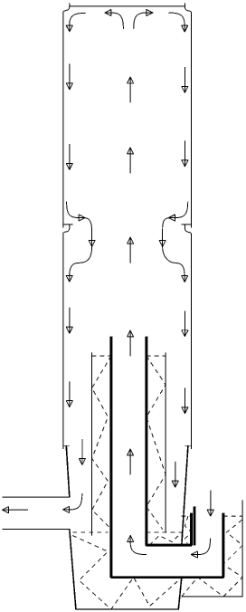 Adding this last insulation made a world of difference, although it'd introduce a problem as well. The 1/8" walls of the feed tube and burn tunnel were eaten up by the fire. In 10 test runs, there were very thin spots in the sides of the feed tube. It became very easy to make a hole by hitting the metal with a small hammer. There's more to write about, I'll post it some time coming week. |
|
|
|
Post by canyon on Oct 9, 2011 8:56:19 GMT -8
Woohooo Peterberg! Your work and your sharing is such a value to me in particular and I postulate this whole community! Thank You!  By the way, I still haven't done a proper one (I've done a rough shaped one out of mortar) but I have intended to do a cyclone after the heat riser for a more effective ash drop, in this case out of stainless steel. Having a different goal of just dropping more ash out into a pan below the cone, I don't think the draft needs will be so great, at least that is my thought and hope. Also, what do you think of turbulators in the heat riser? I have been wanting to try and weld several stainless flat bar pieces across the diameter of a round heat riser in the vertical position to increase turbulance. Could especially help the smaller versions with the layered stream/ cross sectional area ratio issue.  |
|
|
|
Post by peterberg on Oct 10, 2011 0:20:32 GMT -8
canyon, A cyclone which have to separate fine dust from a stream need to be narrow, in order to speed up the spinning of the gases. In that way, gravity will affect the finest particles best. But it'll also cost the largest amount of energy, so I do think it'll slow down the stream too much. About the department of turbulators: I've done something in that area, but I'm not really convinced it will help much. More about that later. And thank you very much for the compliment, it's always good to see someone is appreciating the info.
|
|
|
|
Post by peterberg on Oct 10, 2011 3:37:05 GMT -8
Right from the moment of abandoning the cyclone, there was the notion the normal J-tube has its own drawbacks. To illustrate that, here is a graphic generated in May, and it clearly shows my point. 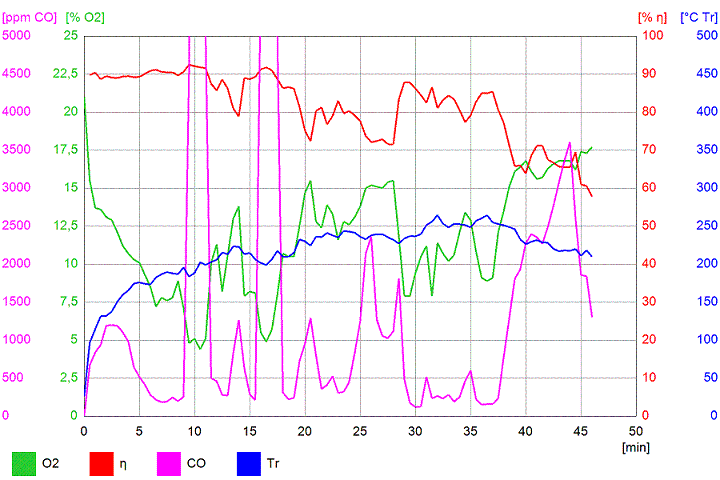 Just about every time the fuel shifts down, the green oxygen line comes down and the purple carbon monoxide line comes up. The last one dramatically, according to the Testo 330-2 easily at 50000 ppm. What I really like to see, is the O2 line coming down and the CO line also. The experiments with the rocket/bell setup showed it's entirely possible to have both levels dancing up and down together instead of opposite each other. By that time I've had the 2nd air stream opening figured out which worked better half of the time, but not very reliable. 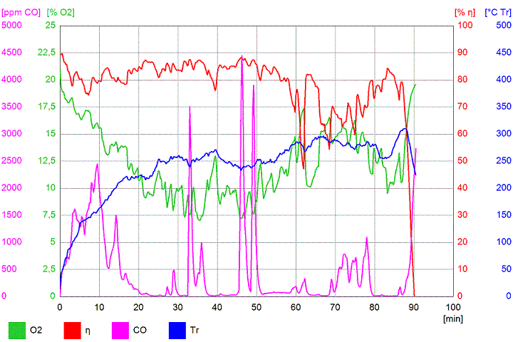 Averages were better now, CO levels were sometimes close to zero. But the burning wasn't as good I was hoping for, yet. Around that time I've moved the whole experiment inside the workshop and used the chimney to vent the gases outside. I've figured out the culprit could be not enough turbulence at the right spot. To this end, I've started to build another rocket in a second garbage bin. With a twist I've been using in the rocket/bell project. In fact it's a J-tube with a syphon inside, just before the entrance to the heat riser. 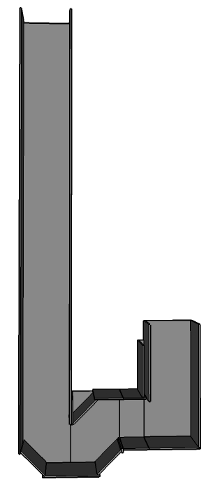 The results of that configuration where sometimes very good, sometimes disappointing. After changing this rocket several times it started to dawn on me: the instances the syphon worked better was when there was a lot of wind. In fact the two versions had an overlapping area where they performed more or less the same. With less wind, the normal J-tube had better results, with high winds the syphon performed very nice. But, both of them weren't reliable enough to my taste. They still had both that spiky behaviour, nothing to rely on. 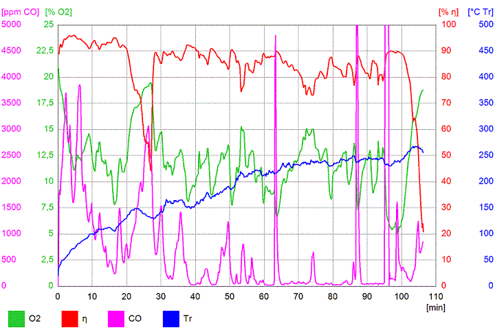 In the same month I've had to replace the square metal tube of the feed tube at both versions. Because the metal went red hot, with a lot of oxygen around. This resulted in very rapidly corrosion, every time after a test run I've had to get the flakes out. Those were dull grey, light weight, almost non-magnetic and very brittle. Conclusion by that time: mild steel isn't suitable for this kind of extreme applications, it will be eaten up by the fire. One clear moment, though. I've tackled the problem of the fire creeping up the feed tube. The heart of that problem is the feed tube which is heating up to the point of self-combustion of the fuel. A way to alleviate this is to actively cool the feed tube. The only means available in my case, is the incoming air from the 2nd air stream. With a lid on the can I've used for insulating the lower end of the feed tube, and a small hole in the front side of the can. By that way, the cold incoming air is streaming around the hot feed tube and down behind it. Of course the insulation is about 2.5" below the lid of the can. Look closely at the next picture: the entrance opening of the 2nd stream is barely visible at the right side of the can. 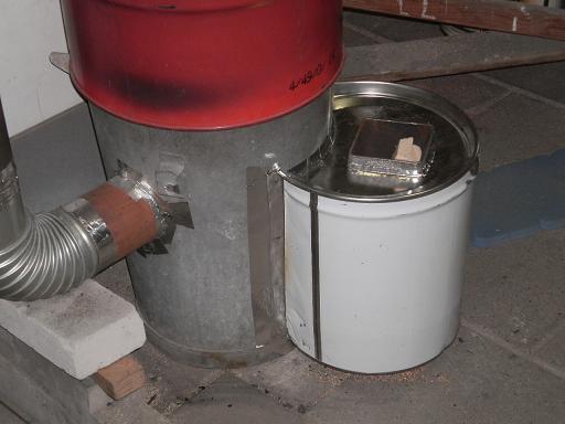 Tomorrow, I'll try to describe the next step to a reliable rocket. I've made that one up from three very different materials. Refractory concrete for the burn tunnel, vermiculite board for the heat riser and mild steel for the top end of the feed tube. |
|
|
|
Post by stovol on Oct 10, 2011 20:24:57 GMT -8
peter, i had in mind trying your siphon system in a cast refractory system with ceramic fiber behind.. mine should look similar to your drawing with one difference... your fire drops straight into the siphon or j.. i thought of trying lowering the fire about three to four inches... making it go up first(the flames) ... turn.... then down the siphon.. then up the riser...hopefully introducing one more area of turbulence.. tho that may require a 4 to 1 riser height as in your small sytem... im just not sure on system sizing..
|
|
|
|
Post by peterberg on Oct 11, 2011 1:09:01 GMT -8
i thought of trying lowering the fire about three to four inches... making it go up first(the flames) ... turn.... then down the siphon.. then up the riser...hopefully introducing one more area of turbulence.. tho that may require a 4 to 1 riser height as in your small sytem... im just not sure on system sizing.. , Maybe you mean something like this: 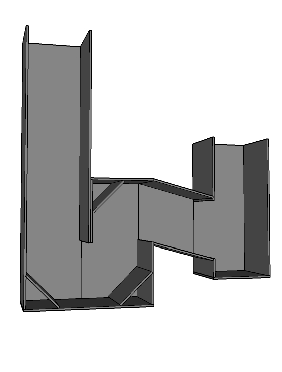 I've tried that as well, it seemed to be such a good idea! There's an ash pit, the flames are guided upwards first, all corners has a sloped plate to guide the stream and on two of that plates I've had a trip wire mounted. Had it running without the plates as well, by the way. In short, it will work, but it didn't fare any better than any of the other syphon constructions. And yes, it required a 3' heat riser. I've tried and tested 6 versions of the 4" rocket prior to the current one. All with different lengths of heat riser, and insulated of course. |
|
|
|
Post by stovol on Oct 11, 2011 5:35:35 GMT -8
Pete , have they all been four inch.. You think the configuration above would perform differently using a 6x6 system size ? I will be building something this week! Is there some configuration you'd like me to try with ceramic blanket and icf? Prob add itc 100 later after I get a tester of some kind (to compare temperatures) .. Thanks bro .. You are the man!
|
|
|
|
Post by peterberg on Oct 11, 2011 7:35:09 GMT -8
Pete , have they all been four inch.. You think the configuration above would perform differently using a 6x6 system size? If you ask me about my opinion: the whole system is simple enough to be scalable. So I expect a 6x6 system wouldn't show any different behavior. No guaranties, though, the proof of the pudding is in the eating. I will be building something this week! Is there some configuration you'd like me to try with ceramic blanket and icf? Please, don't rush things, wait another day before starting with the molds. Description of the most promising configuration is on its way. |
|
|
|
Post by grizbach on Oct 11, 2011 8:23:12 GMT -8
Hello all!
If you ask me, what Peterburg is doing with the syphon, is creating more mixing without turbulators!
I have tried the basic syphon that Peterburg has shown. Making it shallower(less of a dip) helped the draft.(common sense)
grizbach
|
|
|
|
Post by stovol on Oct 11, 2011 8:24:09 GMT -8
Ten four.... Thank you ... I plan on a seventy mile trip to get materials in the next few days
|
|
|
|
Post by stovol on Oct 11, 2011 8:31:02 GMT -8
Hello all! If you ask me, what Peterburg is doing with the syphon, is creating more mixing without turbulators! I have tried the basic syphon that Peterburg has shown. Making it shallower(less of a dip) helped the draft.(common sense) grizbach Griz . Do u have a pic or drawing of your setup with shallow siphon? |
|
|
|
Post by peterberg on Oct 11, 2011 8:48:59 GMT -8
It's not easy to stuff the development of 5 month's time in a few days, and make a report in a language which isn't my native tongue... but here we go. All 6 versions of the metal rocket had some drawbacks. The simplest J-tube had the advantage of working nice but not excellent with a very weak draft, the syphon versions were marginally better on average with very strong draft. All of them were unguided projectiles, impossible to predict. But I've found there's still room for improvement. The main culprit wasn't inability to reach good results, but to produce those results reliable. Mostly when the fuel shifted down the feed tube the CO spikes occurred, and ever so often it corrected itself within a couple of minutes. The cause of the spikes are clearly an overload of volatiles in the burn tunnel. Shortly after that moment the temperature will rise and the burning will stabilize again. Solution to this is not a larger air supply, because that will result in a lower efficiency. Target definition is to promote better turbulence without compromising the ability to run well with weaker draft. One way to do that is to introduce a turbulator in one form or another. Beside the mixed materials I've chosen to do this in three ways. A turbulator at the end of the burn tunnel, the ceiling of the burn tunnel slightly shaped as a tiled roof, and one V-shaped trip wire. The resulting J-shape would look something like this: 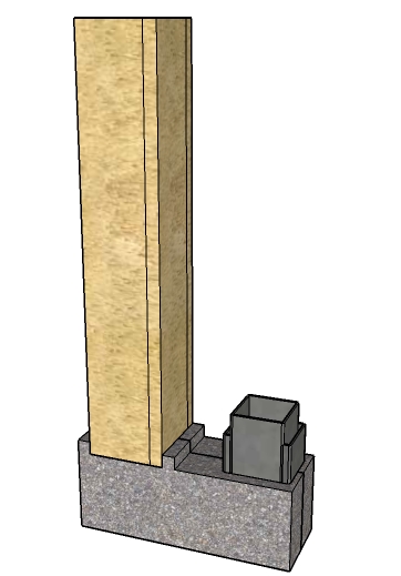 As is visible, the burn tunnel consists of two parts of refractory concrete, the heat riser simply made of vermiculite board held together by screws and the feed tube a relative simple piece of steel with some additions. 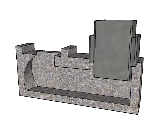 This is how the inside of the tunnel appears: a curved backside of the burn tunnel, the feed is hanging in the concrete. On the feed there's a piece of steel welded to both sides. To support the feed and prevent it from sliding down on the one hand, and to provide an opening for the 2nd air stream on the other. Which is shown by the next picture. 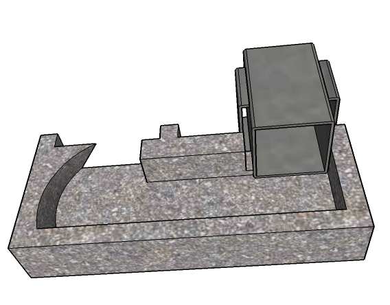 The trip wire isn't shown on this drawing but it is visible in the make-shift mold here. Both sides of the tunnel together forms the trip wire into a V-shape, which is pointing to the riser. The trip wire itself is coming gently down the ceiling of the tunnel, more or less 1/4", to end abrupt in a sharp edge. 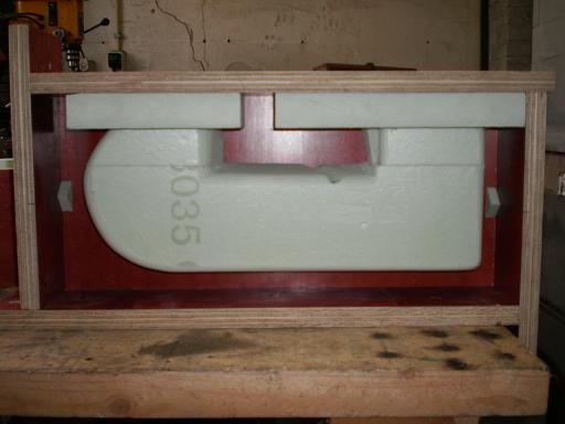 One day later the cast pieces could be released from the mold, mostly by destroying the molds. 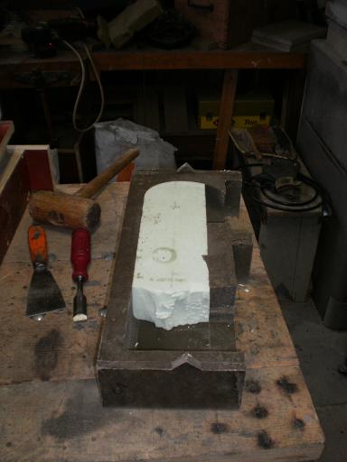 Here the cast pieces are assembled with aluminum silicate felt between them and three pieces of steel wire around it to held it together. 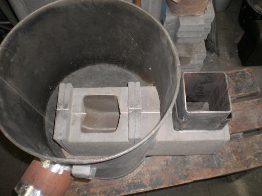 The whole thing inside the garbage bin, ready to accept the heat riser. 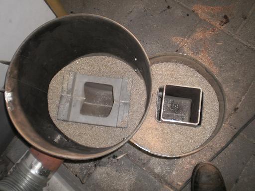 Ready to close the lid around the feed tube, and to mount the two 15 gallon barrels. 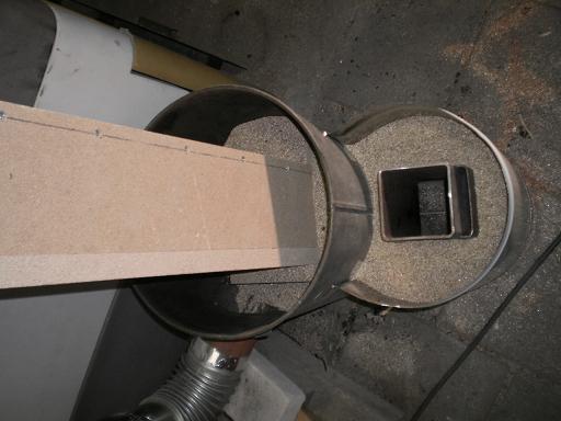 And the whole contraption, looking exactly the same as all the others, with a very different content. 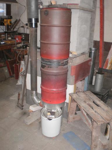 That's about the build, about the performance will be next. |
|
|
|
Post by peterberg on Oct 11, 2011 9:04:42 GMT -8
If you ask me, what Peterburg is doing with the syphon, is creating more mixing without turbulators! I have tried the basic syphon that Peterburg has shown. Making it shallower(less of a dip) helped the draft.(common sense) , Do you mean something like this? Maybe with or without the bended loose insert plate? I've tried that too and you are right, it's making a louder noise. However, the Testo wasn't as impressed as me by the sound. The results were slightly better than the plain vanilla J-tube, but not significantly so, the same spikes persisted. In short, the same capriciously behavior. 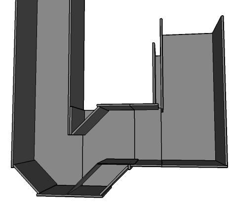 |
|
|
|
Post by grizbach on Oct 12, 2011 0:05:00 GMT -8
stovol, Peterburg, I drew up a quick sketch of what I'm talking about. The idea is to get more than a 90 degree turn going into the heat riser. The one on the left is the one I mentioned. The right is a variant of the idea. grizbach Attachments:
|
|
|
|
Post by stovol on Oct 12, 2011 5:02:25 GMT -8
griz... the one on the right looks like a cool idea... somewhat like the beginnings of a Clarry stove? thanks to all fellow pyros on this board... pete ... your setup was beautiful.. lot of work on the casting.. anxious to see the results...
Has anyone experimented with the zig zag turbulators? i wonder if casting some z shapes in the burn tunnel, right before it turns up the riser, would be beneficial or constrictive? where can a fellow find vermiculite board ? I'm going to get ceramic blanket and insulating castable refractory today! the drying time is going to kill me.. lol
|
|


