|
|
Post by peterberg on Mar 14, 2019 4:23:12 GMT -8
Every answer can generate two more questions. One of those being this one: the restriction in the end port, could that also be done at the riser stub itself? Very close to the all-important riser port, but what isn't tested is still uncertain.
So yesterday evening I widened the end port to 90% of the square riser's csa and restricted the top of the riser stub to 80% of the same. It worked of some sort, coming up to speed was slow and there were some moments of very low O² (3.5%) and CO peaks. Nothing drastic, and above this new restriction the flames formed a recogniseable double vortex during some minutes. Air speed in the firebox was unusually low, as in the port and riser themselves.
Too unstable situation to my taste, verdict seems to be not positive.
Restrictions so close to the port doesn't do any good.
I took out the riser restriction this morning and next question was: how small could the end port be?
I squeezed the end port down to less than 50% of riser csa, smaller than the riser port itself. Slower even than the situation above, very low O², 10 mimutes of CO level that was out of sight. Worse than the situation above, unacceptable.
Next test will be with an end port that is exactly the same as the riser port, during earlier tests end port was slightly wider.
|
|
|
|
Post by peterberg on Mar 15, 2019 13:02:28 GMT -8
End port has been tested with three different configurations: exactly equal csa as the riser port first. The results of this run were mediocre at best, very low O², one CO peak up to 3500 ppm. Conclusion so far: smaller is no good at all, the same is only so-so.
Riser port is still at 57.5% of the square riser's csa. Second run was done with an end port of 67.6% of riser's csa, a full 10% larger than the riser port. I loaded the firebox with large pieces, just 4 of those, with some pine kindling on top. It was a nice run, not very eventful. At 28 minutes into the run I added another medium sized piece of fuel. The core responded by pushing the O² down to 5.3% for a short while, the CO rose just a little bit and all was normal again.
I wasn't really satisfied, so I repeated this run in the same configuration. Smaller pieces of fuel, 8 this time and some kindling, the idea being to provoke the thing and see how stable it would appear. Not bad, not bad at all, O² took a dive down to 4.7% and CO visually did rise quite a bit but nothing drastic or out of scale.
This evening I tried another end port size, being 5% larger as compared to the riser port. As an extra, I added a woven 1/4" glass strip at the top and sides of the tunnel part, just downstream from the riser's mouth. The preceding run looked like there were some darker flames along the sides and I figured a trip wire might be a remedy.
I loaded the firebox with 10 pieces of oak, all quite small so development of the burn would be relatively quick leading to an explosion of burnable gases. Some kindling on top and off it went. The O² level went quite low (5%) early in the burn but CO level barely reacted to it. I will keep this end port size for a while and experiment further with trip wires. And do more runs to verify this wasn't a one-off.
|
|
|
|
Post by independentenergy on Mar 15, 2019 15:06:03 GMT -8
all this is very interesting.
do you think it is possible to use a sidewinder for this system?
|
|
|
|
Post by peterberg on Mar 16, 2019 1:15:29 GMT -8
all this is very interesting. do you think it is possible to use a sidewinder for this system? A sidewinder is entirely possible, yes. The expansion tunnel in such a configuration will be at right angles with the firebox. But due to its length/depth it will stick out at one side, opposite the riser. Not a great problem in case the tunnel is used as an oven since it need to go through the heater's wall anyway. |
|
|
|
Post by peterberg on Mar 16, 2019 3:53:33 GMT -8
This morning I repeated yesterday's run. In order to compare results, here's the yesterday's diagram:  Averages: 11.9 % O², 91.2 % eff., 641 ppm CO, 109.5 ºC (229 ºF) Just a bit of wind, results are very good, CO is about half of what is maximum for the 2022 EU rules. Today's run using larger fuel pieces this time. Three large pieces and two smaller ones on top, kindling on top left. Windy with strong gusts, too strong even for the draft limiter.  Very good again, there are some differences but those are fairly small. Please ignore the fluctuation in the temperature line, reflected in the efficiency line. Most of the time the averages are correct anyway. Averages of today's run: 12.8 % O², 89.8 % eff., 579 ppm CO, 117.6 ºC (244 ºF) Mark the high start & end CO bumps are largely and sometimes completely absent which helps to keep the averages down. The Testo 330 need to be calibrated again, lowest CO in any run is around 150 ppm at times where I'd expect something between zero and 50 ppm. As an observation: by now, those two barrels are too small as heat extraction for this tiny 120 mm (4.72") but powerful core. |
|
|
|
Post by coastalrocketeer on Mar 16, 2019 9:34:07 GMT -8
Anticipation is killing me... Can’t wait for a finalized design and drawings of this core... Thank you for your dedication and hard work Peter!
|
|
|
|
Post by esbjornaneer on Mar 16, 2019 14:38:22 GMT -8
Anticipation is killing me... Can’t wait for a finalized design and drawings of this core... Thank you for your dedication and hard work Peter! I second this statement. Great work Peter! |
|
|
|
Post by peterberg on Mar 17, 2019 1:22:20 GMT -8
Thanks guys, please be patient. In order to be able to produce a true reference design there's more work to be done. In this stage I am quite happy, leaving out most bells and whistles and still achieving good results feels very rewarding. In the Nortern hemisphere spring is on its way, I hope all necessary tasks are ready and done before next fall or maybe midst of summer at the soonest.
For example, there's nothing done to get to a proper door and air inlet assembly, yet. There's a substantial amount of work involved to build and test this, and more money.
|
|
|
|
Post by travis on Mar 17, 2019 23:13:38 GMT -8
Peter this is very exciting! I have been reading through these posts quite a bit and hope make changes to my stove according to what you are doing. Thank you for your dedication!
|
|
|
|
Post by peterberg on Mar 18, 2019 12:50:23 GMT -8
Yesterday during a verification run the trip wire made of braided glass melted. And dripped down from the ceiling and walls of the top box, all in slow motion. Behind the braid there was an adhesive layer which burned away and sent the CO sky high. Logically, one would say, glass will melt between 520 and 700 ºC (968 - 1290 ºF), the topbox/oven could be up to 930 ºC (1710 ºF) occasionally. So the make-shift trip wire was no more, the remnants looked like this: 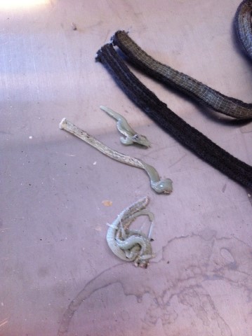 To compare, the black strips on top right is what it used to look like. Today I did another run without it and this failed miserably. Presumably because of the fuel being tinder-dry by now, it has been beside the heater for a week. This is serious, the reference design should be as robust as possible, it need to be able to cope with that. As one can see in the diagram the O² took a dive down to 4% around 12 minutes into the burn and the CO rose out of sight.  So I figured it would be best to try another, classic shape of trip wire. The triangular shape which I used earlier in the J-tube experiments. This would be one of the least obstructive ways to induce small turbulence. 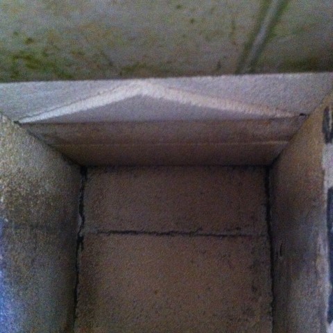 I loaded the firebox very carefully, so no tunnels could be formed during the burn. The less combustible gases are formed at the same time, it would stand a better chance to complete a succesful burn. 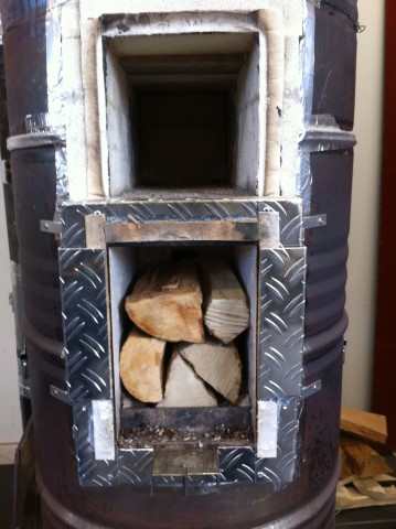 Boy, was I wrong! The oxygen level went down to 4.2% and hovered between 4 and 5% for ten minutes. The test heater got unbelievably hot but... CO refused to go up steeply. Mind you, the weight of the fuel was only a meagre 3 kg (6.6 lbs).  I've never seen such a burn like that, was this because of that unpretentious ridge at the ceiling? Through the top window it was even visable that the center of the horizontal flame curtain remained clear, while the sides seemed to be darker yellow/orange. Tomorrow I'll amend the trip wire into a straight and slightly higher one at right angles to the gas stream. Easier to make and simpler to understand for any first-time builder. When the results are satisfying I'll proceed with that. If not, I'll fabricate an extra trip wire left and right, directly under the horizontal one and test that. Exciting times! |
|
|
|
Post by drooster on Mar 19, 2019 8:38:17 GMT -8
So I figured it would be best to try another, classic shape of trip wire. The triangular shape which I used earlier in the J-tube experiments. This would be one of the least obstructive ways to induce small turbulence. I presume this trip-step brick is carved from IFB like the other bricks in this configuration? |
|
|
|
Post by gadget on Mar 19, 2019 10:50:06 GMT -8
Peter,
When CO goes up while O2 is dropping is that not an increase in combustion? Indicating that you are producing less C? Assuming your draft is not decreasing causing a drop in CO2 and increasing CO
|
|
|
|
Post by peterberg on Mar 19, 2019 12:11:01 GMT -8
I presume this trip-step brick is carved from IFB like the other bricks in this configuration? Yes, it is carved from IFB. The firebox and riser stub assembly are built from ceramic fibre board, the top box out of IFB. |
|
|
|
Post by peterberg on Mar 19, 2019 12:20:56 GMT -8
When CO goes up while O2 is dropping is that not an increase in combustion? Indicating that you are producing less C? Assuming your draft is not decreasing causing a drop in CO2 and increasing CO While O² is dropping this is a sign more oxygen is used, so combustion is increased. Rising CO means the combustion is less complete, since there are more large hydrocarbon molecules which aren't cracked. In many of my published diagrams you see moments that O² is dropping while CO is dropping as well. That's the actual situation that combustion is increased together with an increase of combustion quality. When CO is rising the burn is producing more C, not less. In case CO is high enough, say above 5000 ppm, the burn is producing smoke, i.e. more black carbon. |
|
|
|
Post by gadget on Mar 19, 2019 21:44:17 GMT -8
When CO goes up while O2 is dropping is that not an increase in combustion? Indicating that you are producing less C? Assuming your draft is not decreasing causing a drop in CO2 and increasing CO While O² is dropping this is a sign more oxygen is used, so combustion is increased. Rising CO means the combustion is less complete, since there are more large hydrocarbon molecules which aren't cracked. In many of my published diagrams you see moments that O² is dropping while CO is dropping as well. That's the actual situation that combustion is increased together with an increase of combustion quality. When CO is rising the burn is producing more C, not less. In case CO is high enough, say above 5000 ppm, the burn is producing smoke, i.e. more black carbon. So this is basically to much fuel due to rapid decomposition? That would make sense to me looking at that graph From what I have seen as far as lack of creosote in these heaters, I'm betting any HC's not fully broken down are going to be in the C4 range. Especially with the very high temps. |
|


