|
|
Post by peterberg on Sept 9, 2018 8:52:09 GMT -8
In May of this year Travis built a heater in Mongolia. He was aiming for a simple design, possible to build with local materials and a shorter riser than the recommended size. He succeeded in doing that by making the riser wider towards the top and finally closed it off with a couple of bricks in such a way it went back to the normal riser's cross section area. His riser's dimensions were 58 cm (22.8") high and tapered out from bottom to top, 15 cm (6") square to 25 cm (10") square. Recommended height for such a system would be 108.5 cm (42.7") with a minimum of 86.8 cm (34.2"). So, his riser was about 30 cm or 1' shorter than the recommended minimum. Travis' results seemed to be very good, so I made plans to test such a setup. It did cost me some time to work out what this would mean. I think there could be a rough way to calculate it, by volume to be precise. In order to be able to compare a tapered riser to a straight one, irrespective whether it being square or round. A normal square riser of that size is 15*15*108.5 cm= 24412.5 cm³ in volume. Easier to see that as 24.4 dm³ or liters (1490 cu in). Travis' riser can be calculated as ((2*15+2*25):2)*58= 24650 cm³ equals 24.65 liters (1500 cu in). Assuming this way of comparing is about right Travis' riser could have been even shorter, by building it closer to the equivalent straight minimum one... Being quite curious what that could mean in another system I designed and built a test heater. I'll be back online later with pictures and preliminary test results. |
|
|
|
Post by Dan (Upstate NY, USA) on Sept 10, 2018 6:05:50 GMT -8
And the Travis Taper Riser is born...
|
|
|
|
Post by satamax on Sept 10, 2018 10:03:36 GMT -8
I like just "Travis Taper"
|
|
|
|
Post by peterberg on Sept 10, 2018 11:22:39 GMT -8
Thanks guys, any name would be good. But now to what I did with the idea: I built a 12 cm system in two barrels as the bell enclosure. A straight square riser's volume would be the csa of the riser multiplied by the desired length. In my case I choose to aim for a minimum configuration comparable to a straight riser with a length of close to 70 cm, being 8 times the base figure. So a 12 cm system could be calculated as 12²*70= 10080 cm³ or 10.08 liter. My riser behind the firebox happened to be 31 cm high, this is 12²*31= 4464 or 4.464 liter. This part is just straight because of space constraints. The higher part is tapered from 12² to 20² and 21 cm high. Which is calculated (12²+20²):2= 272 cm² as the average csa of that part. The volume is calculated as 272*21= 5712 cm³ or 5.712 liter. Adding the 4.464 liter of the lower end comes to 10.176 liter. Slightly more than the calculated minimum of a straight riser of the same system size. The height of the top part should be 20.6 cm instead of 21 cm so I am pretty close. The firebox and lower riser are as the Mallorca build, square, chamfered at the back to the level of the port and without backsweep. 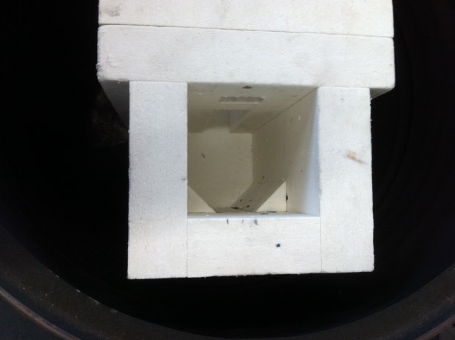 There's a small extra port at the top but I plugged it up later on because it doesn't seem to have any effect. The top part is angled at the front and the sides and straight at the back since that is how it could fit inside the barrels. 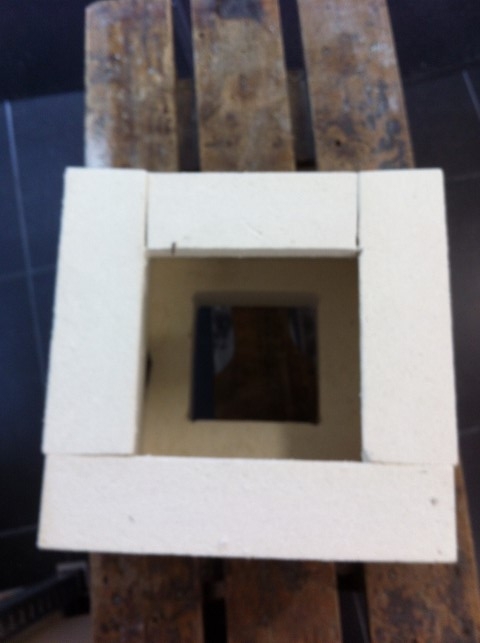 The inside of the firebox looks like this: 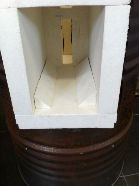 This how the firebox fitted in the lower barrel. 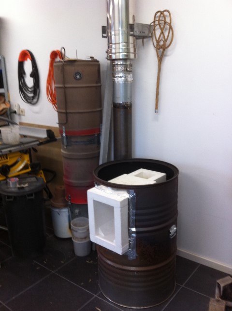 The top piece of the riser is simply placed on the lower part, the ceramic fibre board is very anti-slip. Mark the angled piece has a lid on it, bringing back the csa to 12². 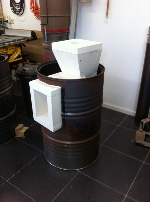 The second barrel placed. 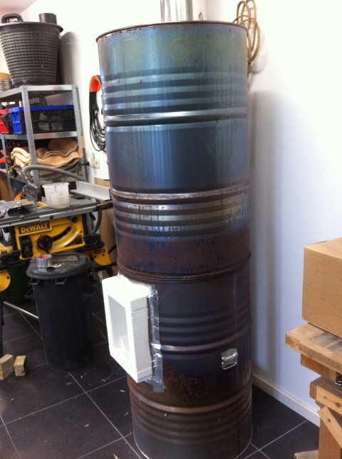 And the first burn in the at the time open system without secondary air provision. 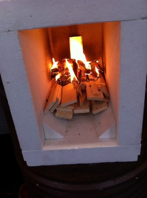 Later on I made some reinforcement of the front, added a floor channel and a piece of ceramic glass as a door. And I uploaded a video to YouTube of a burn complete with front and floor channel. No door/glass at that time. The peculiar sound like a razor in the background is the vacuum pump of the Testo because this happened to be a test run. Tomorrow results so far and more pictures. |
|
|
|
Post by satamax on Sept 10, 2018 13:29:28 GMT -8
Hey Peter, that's quite a strong draft! Don't know if you remember, we had a conversation about cyclonic risers at some point. And my opinion was cone small end on top, and you said cone small end at the bottom. You seem to be nearly there. Planing to try that ? I think i understand this system. A big chamber, behind the port, slows the gases down. Mixing is provided by the port. And the second port acts like a sort of "back pressure" You know, like on two strokes, when the traveling wave comes back in the exhaust, to block the fresh gases to exit via the exhaust port. I am under the impression that your "roar" is faster than usual. This could be because of the back pressure. If this goes mad, we'll have to tune the bells or tubing for a certain amount of back pressure!  |
|
|
|
Post by Vortex on Sept 10, 2018 15:04:06 GMT -8
Nice work Peter. All that ceramic fibre board must have cost you a lot.
|
|
kpl
New Member

Posts: 47 
|
Post by kpl on Sept 10, 2018 20:56:41 GMT -8
At the end, this starts to look like a classic rocket engine, with small burn chamber and then a nozzle. If gases are still expanding after a burn chamber, widening nozzle should really amplify the draft.
|
|
|
|
Post by peterberg on Sept 11, 2018 2:51:52 GMT -8
Don't know if you remember, we had a conversation about cyclonic risers at some point. And my opinion was cone small end on top, and you said cone small end at the bottom. I do remember our discussion about this subject. But I'm inclined to think the aerodynamics are quite different. A cyclone is a quite good dust extractor, I am using a small one between a table saw and a Festool shop vac. The air is sucked or blown in at the wider end at the top and dumps the dust at the bottom while the air blows out through the middle at the top again. Kpl could be right here, it looks more and more like a real rocket engine. Air and gaseous fuel is blown in through a duct, widening into the combustion chamber and blown out at the other end through the same duct as at the beginning. And no, I won't try that cylone idea in the foreseeable future, maybe the one that's posing the idea is the right person to test it?  I am under the impression that your "roar" is faster than usual. This could be because of the back pressure. If this goes mad, we'll have to tune the bells or tubing for a certain amount of back pressure!  Roar is faster than usual, yes. It's on the verge of picking up a very quick pulse when it's heated up. It's also immensely powerful for such a small device, those two barrels aren't enough to extract enough heat most of the burn. Maybe a less favourable chimney stack would take it down somewhat. And yes, Trevor, that ceramic fibre board is horrendously expensive. I've payed almost €200.- for two sheets including transport on a pallet. The sheets are 120x100x5 cm, I managed to use one sheet for the whole of this batchrocket. It's dusty material, I kept scratching my head for days after the build. And the first cm thickness at the hot side shrinks quite a bit. |
|
Ralf
New Member

Posts: 42 
|
Post by Ralf on Sept 11, 2018 3:57:16 GMT -8
Hi Peter,
could it be that the high efficiency and power is partly due to using that fibre board throuhgout ?
There´s nothing that robs any heat from the combustion and also almost no mass that has to heat up to operating temperature.
Can you make a guess on how a firebrick version of this that´s only insulated on the outside would perform ?
(apart from me having no idea yet of how this could be built without an awful lot of cutting)
|
|
|
|
Post by satamax on Sept 11, 2018 4:55:16 GMT -8
Kpl could be right here, it looks more and more like a real rocket engine. Air and gaseous fuel is blown in througn a duct, widening into the combustion chamber and blown out at the other end through the same duct as at the beginning. Yes, absolutely right, it is on the same line as a rocket engine. Tho, the rocket engine doesn't require much mixing. One of those days, we'll end up making a wood fired valveless pulse jet!  About cyclonic, do you remember this one? My first.  Cyclonic J tube, the horizontal tube enters the gas bottle, until the center, it's called a neutral vane. For better turbulence, i should have cut it against the circumference of the gas bottle. But i might get back at some point, to something along those lines. |
|
furno
New Member

Posts: 23
|
Post by furno on Sept 11, 2018 6:36:37 GMT -8
The Russian engineer Kolevatov proposed a riser with a variable diameter. The main idea was the flow turbulence. He described it in the book " The Stoves of the New Generation" |
|
|
|
Post by peterberg on Sept 11, 2018 7:00:22 GMT -8
Hi Peter, could it be that the high efficiency and power is partly due to using that fibre board throuhgout ? There´s nothing that robs any heat from the combustion and also almost no mass that has to heat up to operating temperature. Can you make a guess on how a firebrick version of this that´s only insulated on the outside would perform ? (apart from me having no idea yet of how this could be built without an awful lot of cutting) Broadly speaking, the difference between board and brick is the time until the interior of the core is up to working temperature. The heat is delivered much faster than the bricks are able to absorb it, so at some point during the burn there isn't a difference anymore or this is neglectable. I used the same enclosure prototyping the double shoebox which was build out of castable refractory. At some point during every burn it went haywire and couldn't be controlled anymore. In my own heater the firebox is entirely inside the bell enclosure but isn't insulated at all. The riser is another story, temperatures are much higher there. Cutting could be limited by stepping the riser out instead of sloping. That's what Travis did and I'd think it would work just as well. Not tried that yet! |
|
|
|
Post by peterberg on Sept 11, 2018 7:41:13 GMT -8
OK, today's testrun is done. Here are some of the diagrams of the runs of the last 6 days, the worst ones where the CO is going through the roof are left out. 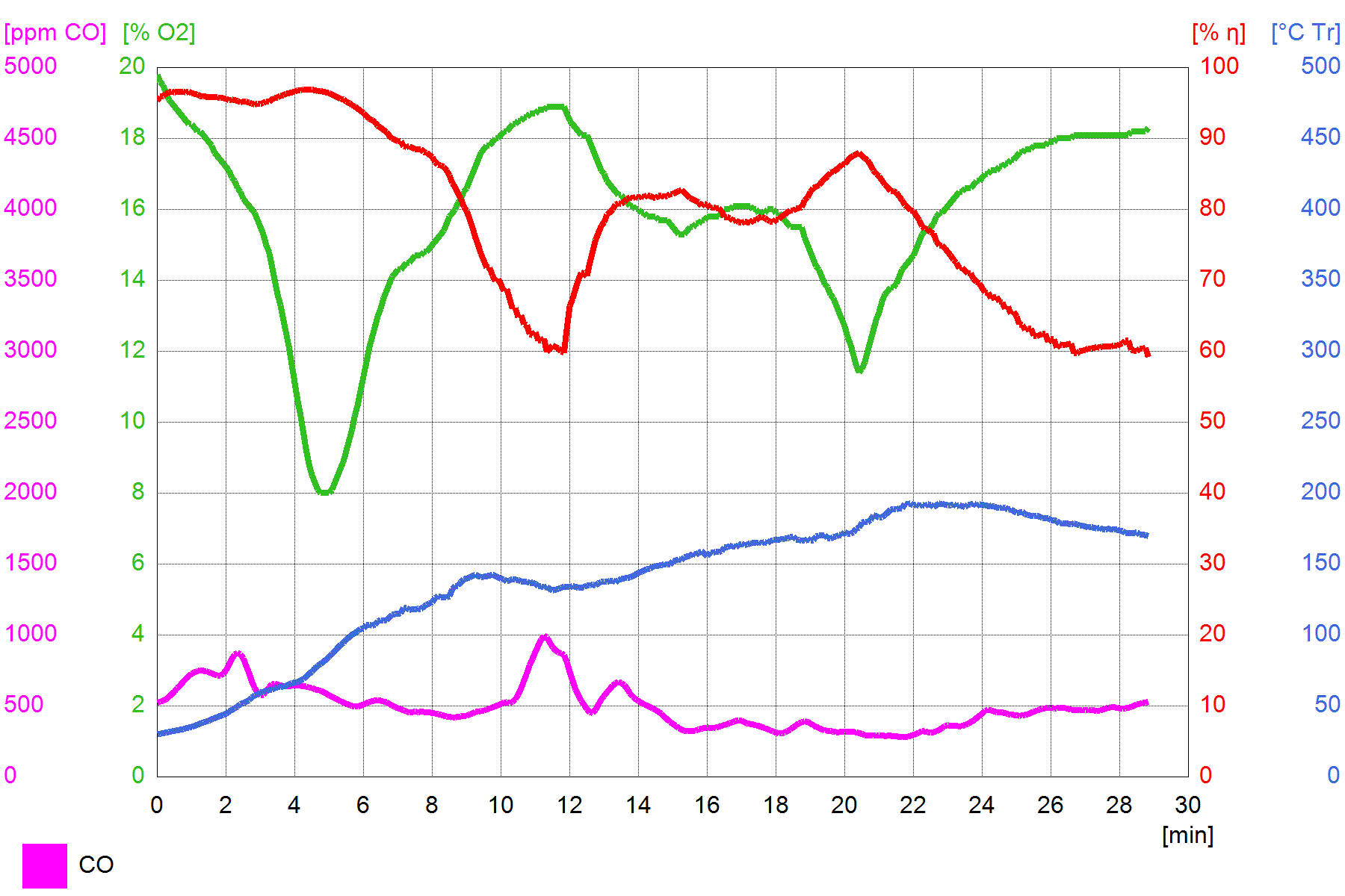 The above is what can be done with an open system, no secondary air but coupled to a decent chimney stack. The CO is quite tame and comparatively low and O² is going up and down like a drunken sparrow. 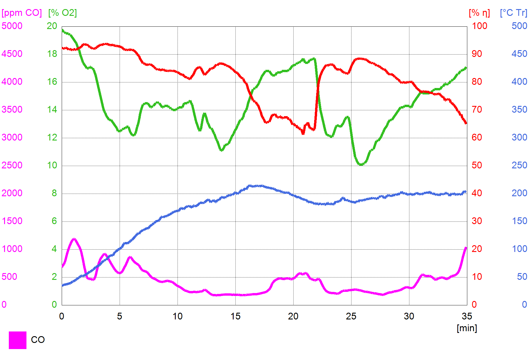 An added floor channel didn't help much, the majority of the air is still going through the firebox itself. Consequently, the floor channel isn't cooled sufficiently so I could see it was cherry red at the end. 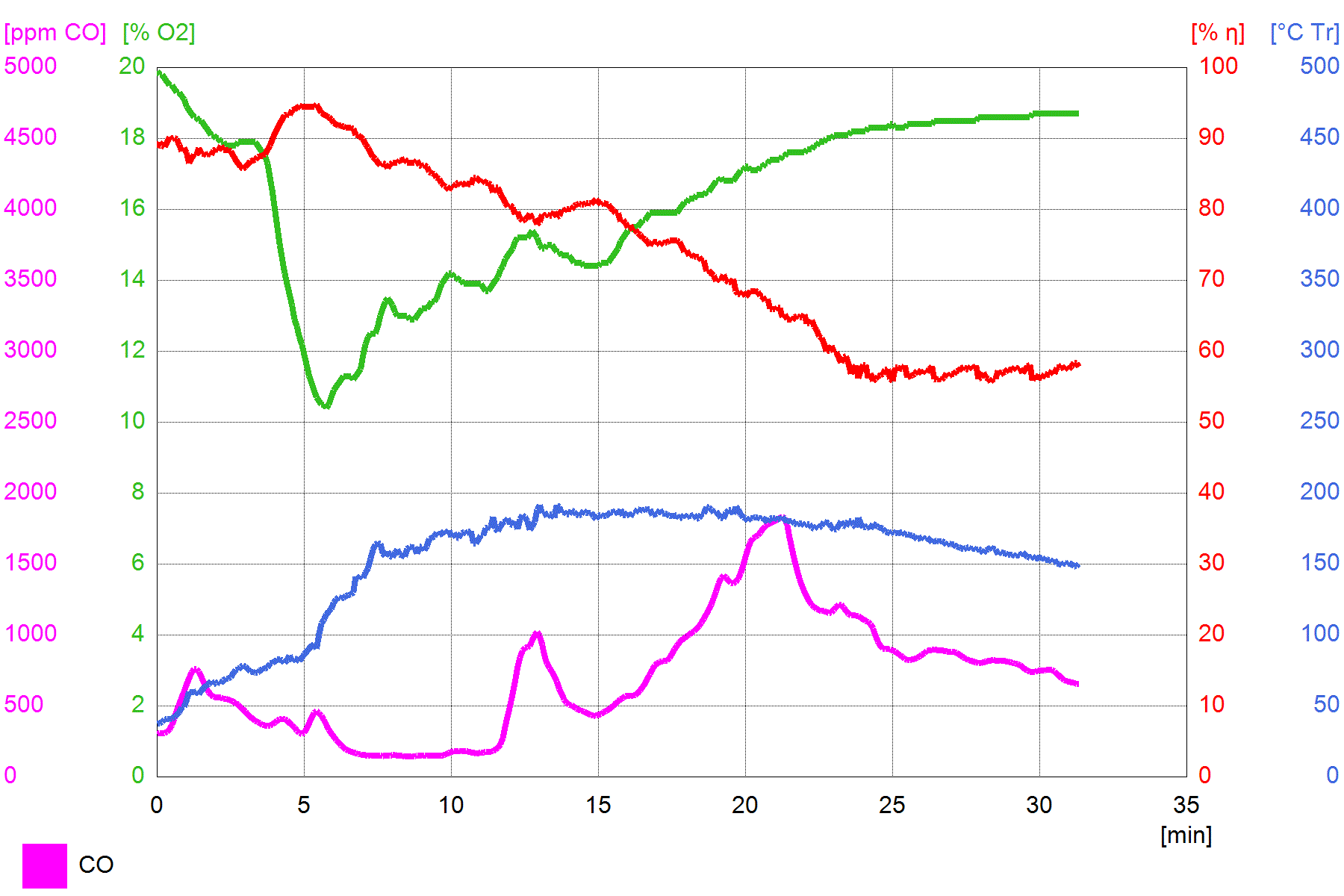 This is a run with a restricted door opening (piece of high-temp glass) and a threshold which brings the air inlet higher up. Still too much air and not stable enough to my taste. 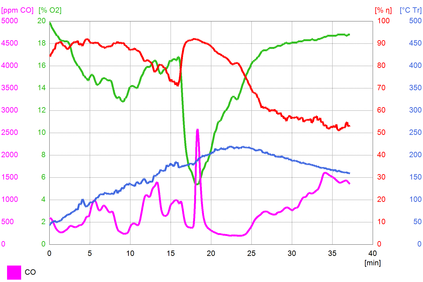 This a fine example of a run which went haywire due to a slow pulse like a locomotive. The idea is that the shape of the CO line (purple) is broadly the same shape as the O² line (green). Without bumps and sharp peaks like this diagram. 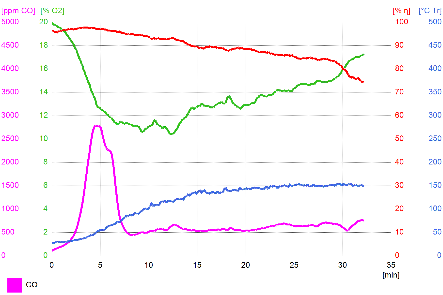 It's getting better although the peak at the beginning is much too high. The glass piece is now lowered and the threshold behind it is down from 60 mm to 40 mm. 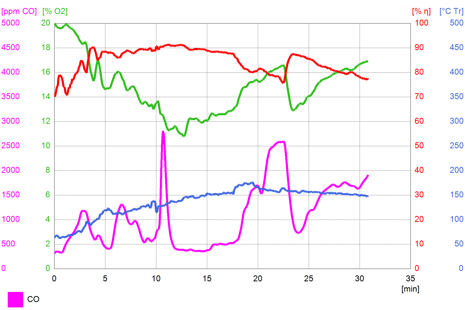 During this run I changed the threshold a couple of times, added fuel, larger and smaller primary air and at last took out the threshold entirely, at 22 minutes where the CO took a sharp dive. 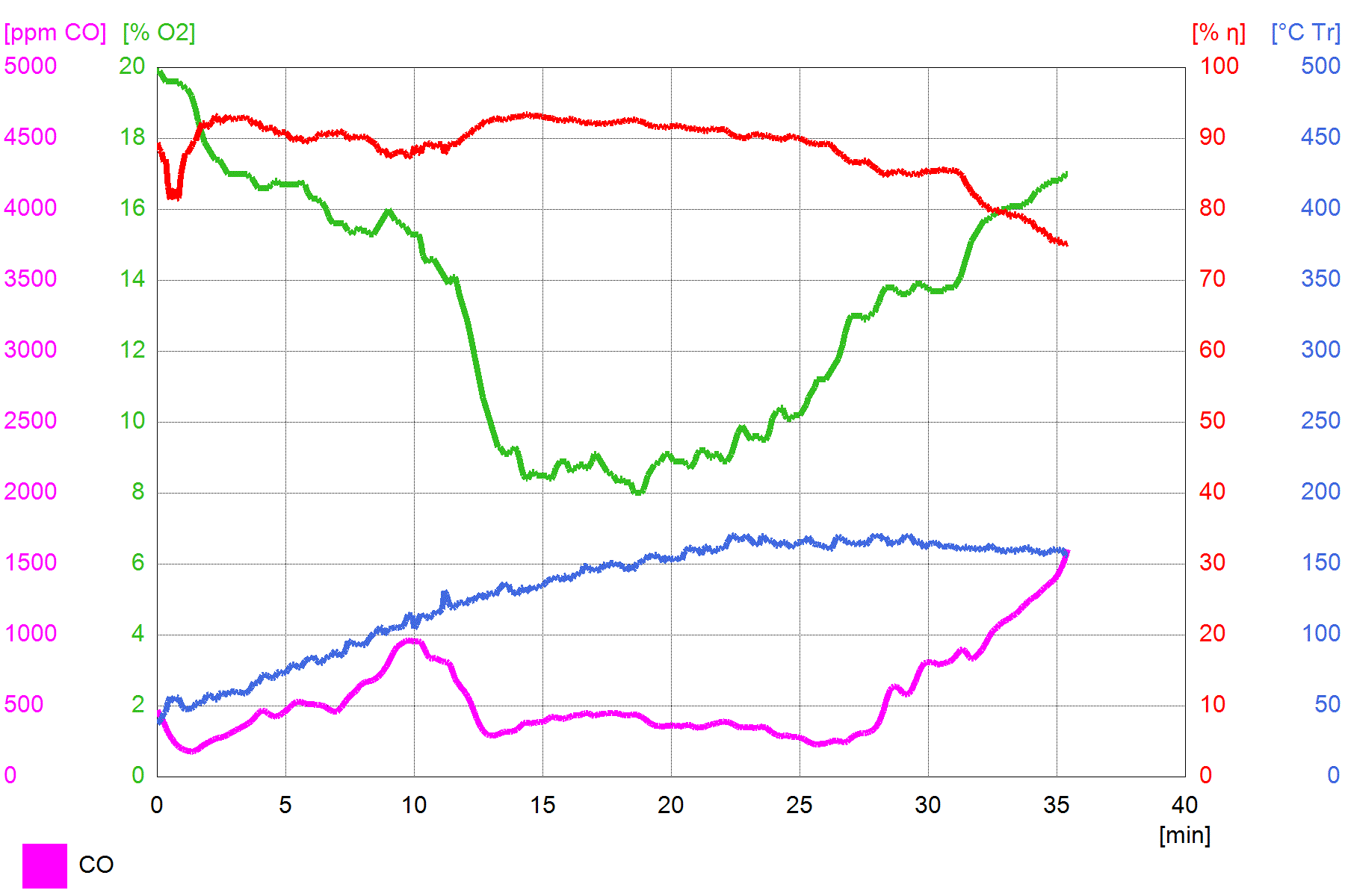 This is more like it, I hope to repeat this run a couple of times. No threshold to begin with, the primary inlet just 12 cm² and as low as possible, secondary inlet fully open which happened to be the same value. Pieces of beech and oak, very dry, loaded as a batch and lit on top. My gas analizer should have been calibrated 6 months ago, the CO values aren't coming down as low as I expected. The white filters of the probe comes out as very light grey, I am able to use those about 8 times before they are becoming dark grey. I'll change it at that point otherwise I can't see what is happening with soot deposits. |
|
|
|
Post by peterberg on Sept 11, 2018 8:07:43 GMT -8
To wrap it up for today, here's a couple of pictures and a short video. I still feel my fingers, the thing is getting awfully hot, even through the glass. 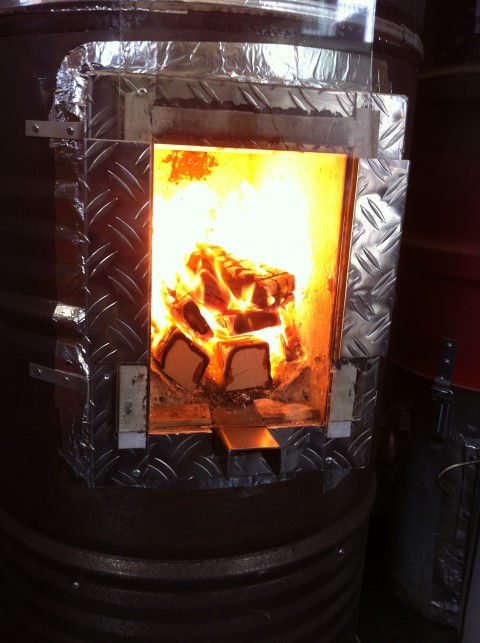 Loaded with beech scraps, very dry, batch loaded, lit on top. 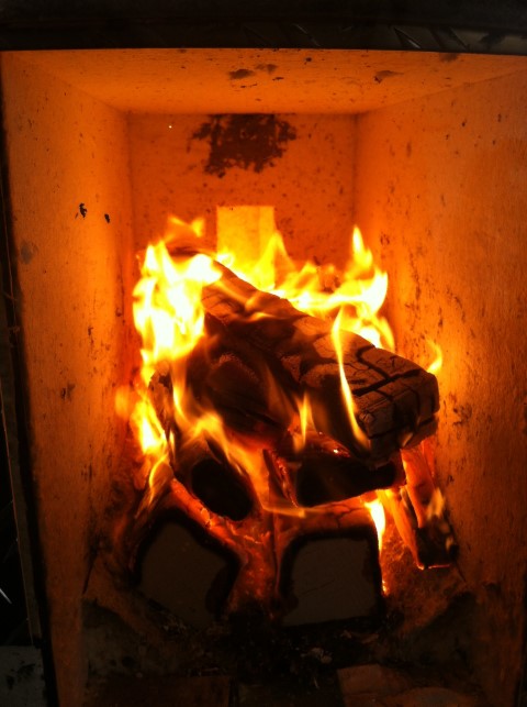 And the video, just before the end you can hear me saying "ooww!" |
|
Reba
New Member

Posts: 2 
|
Post by Reba on Sept 12, 2018 1:20:38 GMT -8
Peter, - the blue line in the picture, this is where you measured it?
Is it the temperature? Where?
|
|