|
|
Post by Vortex on Jan 3, 2018 13:48:11 GMT -8
These small compact high mass cookstoves have a very short window of opportunity to extract the heat before it's gone up the chimney, so I often wonder if insulating the core will result in any actual increase in efficiency. With a dense firebrick core it absorbs heat in the first half of the burn, but radiates it back into the fire in the second half, thus raising the temperature in the firebox more than insulation could have, so maybe it equals out over the whole burn.
|
|
|
|
Post by Orange on Jan 4, 2018 7:04:23 GMT -8
yes yasin your measurments are standard, I've calculated wrong.
I was thinking about the classic insulation on the outside of the firebox and riser. So if you use 6cm thick firebrick, you can substitute it for 2cm firebrick + 5cm air-concrete on the opposite side. That would result in let's say +200C more in the firebox and perhaps better combustion efficiency.
Then you can put more pillars in the bell to increase ISA and overall efficiency.
But you already have 97% combustion efficiency without any insulation which is puzzling. That would suggest that people with completely ceramic fibre boxes have over >100% combustion efficiency and that the methology is incorrent.
|
|
Deleted
Deleted Member
Posts: 0
|
Post by Deleted on Jan 4, 2018 8:15:04 GMT -8
Hi Orange, About combustion effiency, they surely are not above 100% with ceramic fibre fireboxes.. it's rather than it takes A LOT of efforts to get the last few percents. Plus I haven't seen the benefits of insulating the outside of the firebox. Have you seen any chart or something ? Like Vortex said, I'm not sure it will increase efficiency.. About the pillars, it's not so simple.. I don't believe anymore that the statification occurs so well in any kind of bells. You have the speed of the gases, the positions of the opening and the exit of the bell, the way pillars are positioned.. I think all that contribute to the even or uneven heating pattern. When I was taught about hot water systems, I was told to use Tichelmann's systems in which every molecule must find the same resistance on it's path, no matter what path it follows. It seems closer to the truth in my opinion. 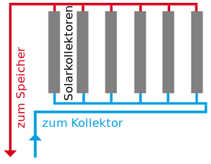 Regards, |
|
|
|
Post by pyrophile on Jan 4, 2018 16:02:18 GMT -8
Hi Yasin, It is typically a second bell positioned below the first one, à la Groum Grzimailo. In his book, he explains how hot gases coming from a first upon bell into a second below bell or gases coming from the upper part of a bell divide in equal currents while cooling as they go down to the bottom of the bell. His mathematical explanation : heatkit.com/docs/advanced/Pages%20from%20TheFlowOfGasesInFurnaces.pdfModern Pottery kilns were made this way at the end of the era of wood kilns, following Groum Grzimailo works. Bricks or potteries are columns and narrow ways between them are ways for gases. I must find drawings... |
|
|
|
Post by rakettimuurari on Jan 5, 2018 2:10:09 GMT -8
Hi Yasin, It is typically a second bell positioned below the first one, à la Groum Grzimailo. In his book, he explains how hot gases coming from a first upon bell into a second below bell or gases coming from the upper part of a bell divide in equal currents while cooling as they go down to the bottom of the bell. His mathematical explanation : heatkit.com/docs/advanced/Pages%20from%20TheFlowOfGasesInFurnaces.pdfModern Pottery kilns were made this way at the end of the era of wood kilns, following Groum Grzimailo works. Bricks or potteries are columns and narrow ways between them are ways for gases. I must find drawings... Excellent piece of info! My thanks! |
|
|
|
Post by coastalrocketeer on Jan 5, 2018 13:51:18 GMT -8
|
|
|
|
Post by esbjornaneer on Jan 6, 2018 3:50:56 GMT -8
Costal, the link from Pyro opens for me and it seems to be pages number 87-92 that have been extracted. Not sure if the pages will be the same in your link.  |
|
|
|
Post by pyrophile on Jan 7, 2018 6:32:56 GMT -8
Great! I didn't know that the entire book could be read in english!It seems to have more pages than my french 1920 version. I acn put the french version if somebody is interested! He speaks about kilns p114 of his book, here : ia600207.us.archive.org/25/items/TheFlowOfGasesInFurnaces/TheFlowOfGasesInFurnaces.pdf Can somebody help me to put the image page 114? thanks! The first drawing could be considered as a single bell like Peter's big bell in his red stove. The second drawing is like many russian stoves with the second bell upon the first one. The third drawing is like the teplushka, rural oven/stove developped later by Podgorodnikov : the first bell is upon and sends hot gases to the second beloww bell through holes made in the bottom. 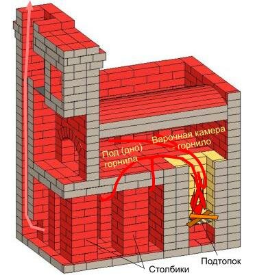 This second solution, very good, could be used in our stoves and would simplify the problem of the by-pass!The first bell would be upon the second one and would get vthe very hot gases from the heat riser. The by-pass would be in this first hot bell anywhere not to high (in order to stay away from big heat) Then gases would go down to the second bell, below, with or without columns. Two or four opposite holes could separate both bells in order to divide the gases in relatively equals streams. That's what did Chernov in his small mass stove : the oven is the first upon bell where flames appear and where two holes '(front left not very visible and rear right) let gases going down to the second bell below. 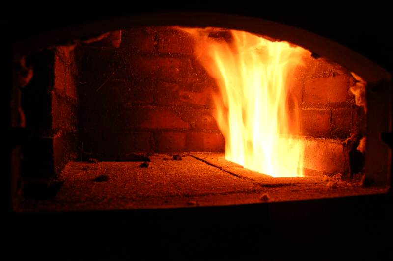 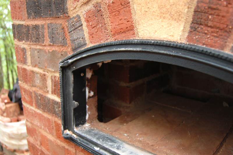 ![]() Yasin, it is also a solution for cookstoves... Benoit |
|
Deleted
Deleted Member
Posts: 0
|
Post by Deleted on Jan 7, 2018 6:54:41 GMT -8
|
|
Deleted
Deleted Member
Posts: 0
|
Post by Deleted on Jan 7, 2018 7:05:18 GMT -8
For the bells and what I was saying to Orange, here is a picture of the last bell of a heater that doesn't work well in my opinion (the gases shortcut a part of the bell) because it doesn't respect the tichelmann rules. It's shown at the second image at the second row : www.krosnis.pl/piec-romana/The gases won't go in the middle of the three columns because there is more friction (the path is narrower) there than in the rest of the bell. I think that the gases come in the left top corner and go at the bottom right corner. Except for these narrower channels, the design of this bell is very close to tichelmann's rules. Regards, |
|
|
|
Post by pyrophile on Jan 7, 2018 7:40:40 GMT -8
Yasin, About Chernov's stove : it was made a few years ago, during MHA meeting in 2012 : no plans but many photos! It is an easy to buld stove but I fear the combustion is not very good...Here : www.mha-net.org/docs/v8n2/wildac12g.htmAbove the oven there is another bell, the third one. The stove finished : 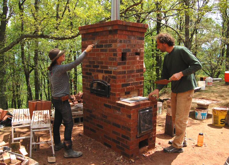 Behind the firebox (in front) , there are three holes. Two allow hot gases to leave the oven (where there is the trowel) down to the second bell . The third hole, behind at the right is the cheminey leaving the second bell below. It brings the cold gases to the third bell upon the oven : 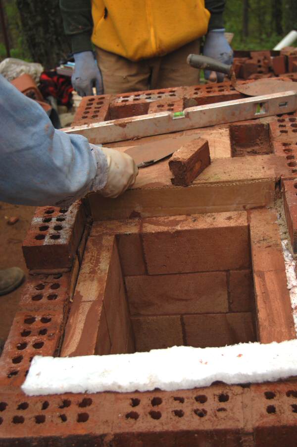 The same with the exit of the firebox (behind the cooking plate and, behind, the flat surface of the oven (with a trowel on it= : 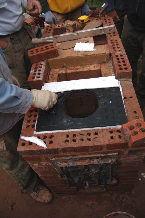 The second bell and the exit to the third bell : 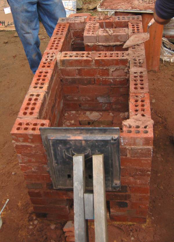 The oven, the two holes going down and the cheminey/exit : 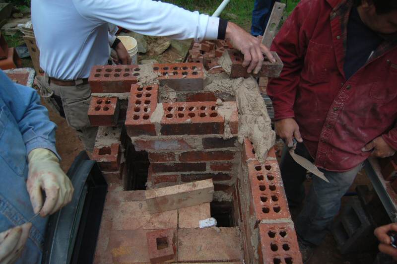 About the stove www.krosnis.pl/piec-romana/ : yes, the columns are very narrow. Kuznetsov lets 13 cm between columns! I watch your other thread! Benoit |
|
|
|
Post by patamos on Jan 7, 2018 9:16:53 GMT -8
Tichelmann's principles always remind me of fluvial hydrology. The way water behaves in streams and ponds… stronger central currents… core trajectories… more friction closer to shore… eddies… and turbulence pillows… forcing the flow this way and that as water always takes the path of least resistance. Although hydraulic forces are less at play in the behaviour of flue gasses, and thermal buoyancy more so… the gasses are more likely to mingle into the nooks and crannies between pillars etc, when they are ponding rather than streaming. So, much depends on intake and exit port flow rates relative to bell volume… hope i'm not too far out to lunch on this reasoning  |
|
|
|
Post by coastalrocketeer on Jan 7, 2018 16:34:43 GMT -8
Costal, the link from Pyro opens for me and it seems to be pages number 87-92 that have been extracted. Not sure if the pages will be the same in your link.  Thank you E... Going by page numbers that would be the beginning of the section entitled "principals for the rational construction of furnaces" |
|
|
|
Post by coastalrocketeer on Jan 7, 2018 16:43:33 GMT -8
So, much depends on intake and exit port flow rates relative to bell volume… hope i'm not too far out to lunch on this reasoning  A hydraulic example might be the difference between the water pushed by the same amount of pressure, passing through the open end of my garden hose, versus a narrow jet nozzle that shoots a high velocity stream (at a lower lpm flow rate with a given pressure behind it) The jet will cause much more disruption/movement in the water of the pond I place it submerged at the edge of. At the higher velocity, LESS water agitates the pond MORE, with less total liters/gallons of water flow. The effect may be less/different with the low pressures and viscosity of gasses in a "furnace", but the effect of transferring more kinetic energy into the bell(pond) and disrupting thermal stratification is the same. |
|
|
|
Post by coastalrocketeer on Jan 7, 2018 17:00:38 GMT -8
This makes my mind rove back to a video on an interesting thermal stratification system used in huge thermal battery water tanks to create "zero net energy" homes in Alaska, and wonder if similar principals could be "turned upside down" and applied to the thermal stratification, and thus, heat scavenging efficiency, of our "furnaces" They use 5k to 15k gallon insulated water tanks inside the structure, and solar thermal arrays to store solar energy all through the 20+ hour summer days to carry through the bitingly cold and dark winters... Literally months of heat storage for the well insulated structures, in those tanks. The most applicable bit to this conversation is their hot water return assembly from the collectors. It uses a VERY wide pipe going down the tank with flaps that let hot water out where it's buoyancy and weight match the existing stratification layers in the tank without disruptive kinetic energy being introduced, with an even wider "Swiss cheese" pipe with holes in it that acts as a "diffuser" for the water exiting it's particular thermal stratification zone flap valve. (At least that's the way remember it, but it's been a year or so since I watched any of the videos) I'll see if I can link the part of one of their very long and interesting presentations where they describe it. (Jump to 1:59:49 in this video since it won't seem to link the time properly) www.youtube.com/watch?v=Xen_VWyDezY&t=119m49s When I have a little more time I will find the video where they describe/show it in better detail.. The designers of these systems were Reina LLC. This is their YouTube Channel. www.youtube.com/user/REINALLC All of their videos are quite long and interesting, so it may take me a bit to fill the link placeholder above where they describe the hydraulic thermal stratification assembly. (I realize passive flaps are not possible/desirable with the low pressures, weight, and viscosity in a flue gas system, but the design, imagined upside down, may inspire similar more applicable forms for designing our gas flow entry into bells that it minimizes introduction of excess kinetic energy into the thermally stratified gas pool, or successfully diffuses such kinetic energy once the gasses are within the bell, but before they enter the main stratification area, with the exhaust, just as their system does with H2O.) |
|