|
|
Post by peterberg on Jun 18, 2018 9:41:17 GMT -8
The width of the port is more than 50 mm anyway, so in my opinion you could use 40x60x2 mm without trouble. Unless your planned system is smaller than 150 mm?
Entering halfway through the port is fairly critical, yes. Having it tapered on both ends isn't that good in my experience but tapered on the hot end is OK. See the floor channel in the now more or less standard BBR, the vertical part is about twice as large as the horizontal part.
|
|
|
|
Post by satamax on Jun 18, 2018 21:12:11 GMT -8
Peter, daft question, are the measurements on the dsr, sorted out completely now? I mean definite.
|
|
|
|
Post by smarty on Jun 24, 2018 2:04:24 GMT -8
Peter. In the sketchup drawing (Abbey one) you built the space in front of the switchback wall (between the port and the outlet to the chimney) as less than the CSA of the rest. Is that how I should make it?
Should I narrow the hot end outlet of the 40x60x2mm box section to the same as 40x50x2mm? Or is it not that critical?
What is the air intake on the door in this model? The secondary is obviously 50x40 but what is the optimum primary?
I’m almost ready to test it with a pizza oven off to the side of the exit chamber I’ll post the results hopefully next weekend if the kiln shelves I ordered for the shelf and top arrive in time. It’s basically a mini-bell off to the side just big enough and tall enough to fit a pizza in.
I made the whole thing in insulating firebricks but I might swap out some of these -at least in the base of the firebox - for medium density firebricks when I finish testing it.
|
|
|
|
Post by smarty on Jun 26, 2018 0:43:27 GMT -8
So I’m trying to get my head around the principles of the top chamber shown in the Abbey sketchup drawing.
Based on a CSA system size of 17,671mm2, or a circle with radius 75mm, I have the following:-
Top port from firebox into chamber = 10,126mm2, or about 57% system size.
Top chamber tunnel = 29,714mm2, or about 168% system size.
Switchback corner = 27,745, or about 158% system size.
Exit port = 27,556mm2, or about 157% system size.
I take it that the larger chamber tunnel sizing is to slow down the gasses, a bit like a stepped wider heat riser would do?
The entry port, switchback corner and exit port are all related in sizing by the CSA of the entry port being added to the CSA of the system? And the chamber dimensions being an additional 10% on top of the previous?
Does this seem like a fair analysis?
|
|
|
|
Post by peterberg on Jun 27, 2018 0:12:44 GMT -8
What I tried to do is to make the whole tunnel/switchback/exhaust 150% of system size or more. Slowing down the gases is one goal, the other one give enough room to the flames to burn out without any restriction.
Sizing is a bit more complicated as compared to the standard batchrocket, all dimensions are related to the chimney size. Riser CSA can't be used anymore because it's laying flat and is larger than before.
|
|
|
|
Post by peterberg on Jun 27, 2018 0:15:49 GMT -8
Peter, daft question, are the measurements on the dsr, sorted out completely now? I mean definite. Nothing definite, status is still experimental. I know it need to be sorted out but I don't have the energy and time to do it. Sorry for my late answer, we are very busy refurbishing our furniture. |
|
|
|
Post by satamax on Jun 27, 2018 2:22:06 GMT -8
Ney worries Peter.
I should do some work myself.
|
|
|
|
Post by smarty on Jul 2, 2018 7:25:27 GMT -8
If I include a threshold I gather that the secondary air goes through this at the base, so I imagine that the primary air goes above the height of the threshold? I was going to make the threshold 100mm tall. Is that about right?
Also the bricks I used are the same width and length as those in the Abbey version but mine are thicker. 75mm instead of 64mm. I’ve managed to make all the dimensions the same as in the sketchup model but the port is deeper on account of the thickness of the brick! I’m hoping it’s not a problem?
|
|
|
|
Post by peterberg on Jul 2, 2018 8:04:47 GMT -8
In a 150 mm system the threshold (or doorstep, whatever you prefer) is 70 mm. The primary and secondary inlet are combined, opening at the level of secondary channel works best. Some 40 to 50 mm between door and threshold would provide space for the primary air going up and over the threshold.
Depth of the port is OK as long it isn't approaching 100 mm which happened to be a critical dimension in earlier experiments.
|
|
|
|
Post by smarty on Jul 2, 2018 9:55:24 GMT -8
Here is where I’m at so far. The low wall of firebricks to the right is going to have akiln shelf on and then another raised on more bricks above it as a roof. The pizzas will go on the lower shelf. Does it look like it might work? Should I put another exit flue in the far right corner to draw the hot gas through or leave it as it is? What do you reckon? The other photo is of the door closed onto the threshold, which I’ve just cut down to 70mm high. The door has a 60mmx60mm square in it as primary air. The lower hole for secondary is 60x40mm. Would this work? Is it something like you meant? app.box.com/s/24n776ow9ubzagplxtd9rc56vwz5dqhb |
|
|
|
Post by peterberg on Jul 2, 2018 11:33:18 GMT -8
I don't know how to put it, I tried to explain the principles to quite some people lately and it seems to be hard to grasp. I'll try it again, but I can only use other words to tell the same thing. The threshold is piece of steel on top and sides of the secondary air channel. The single air inlet opening is at the level of that same channel. The space between the door and the threshold is 40 to 50 mm in horizontal direction so the air which is needed for the primary air need to go up first before it is able to enter the firebox. The temperature difference between incoming air and the firebox is progessively higher during the burn and the colder air tends to stay low, thereby feeding the floor channel at a higher rate at the expense of primary air. This is all there is, it's a system ran by itself to get progressively more air in the floor channel where and when it's needed most. To illustrate, I hacked another drawing and saved some pictures. 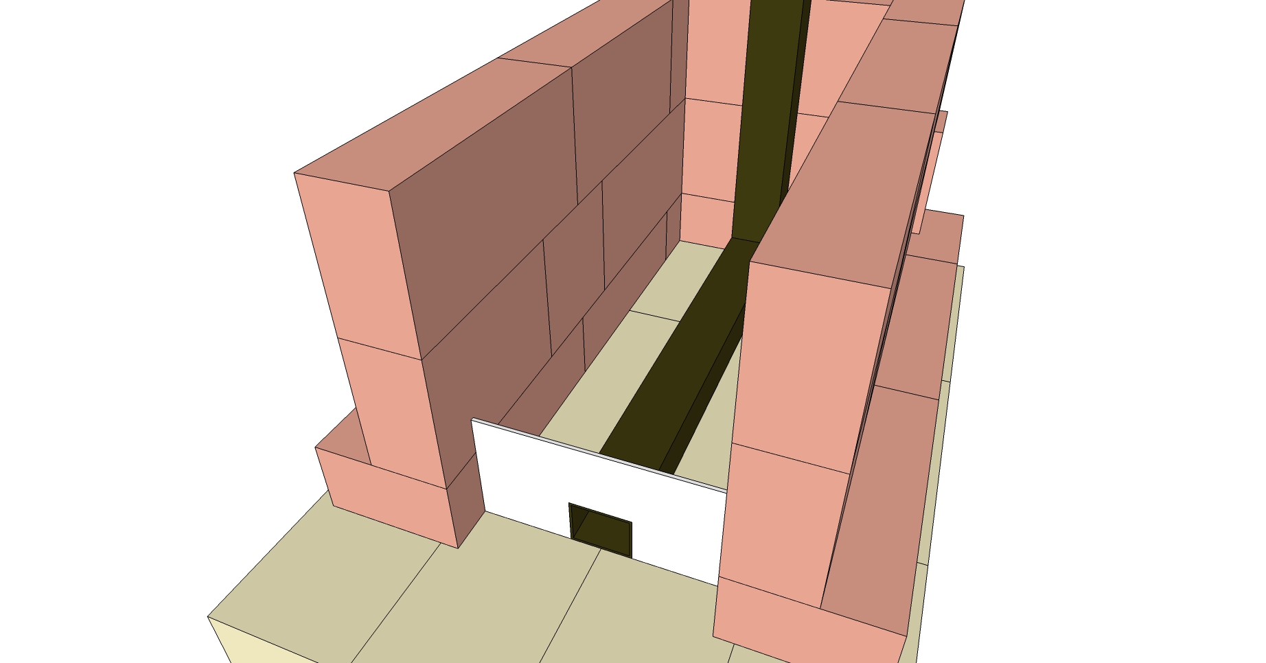 First utilizing a flat floor in the firebox, second with sloped sides. 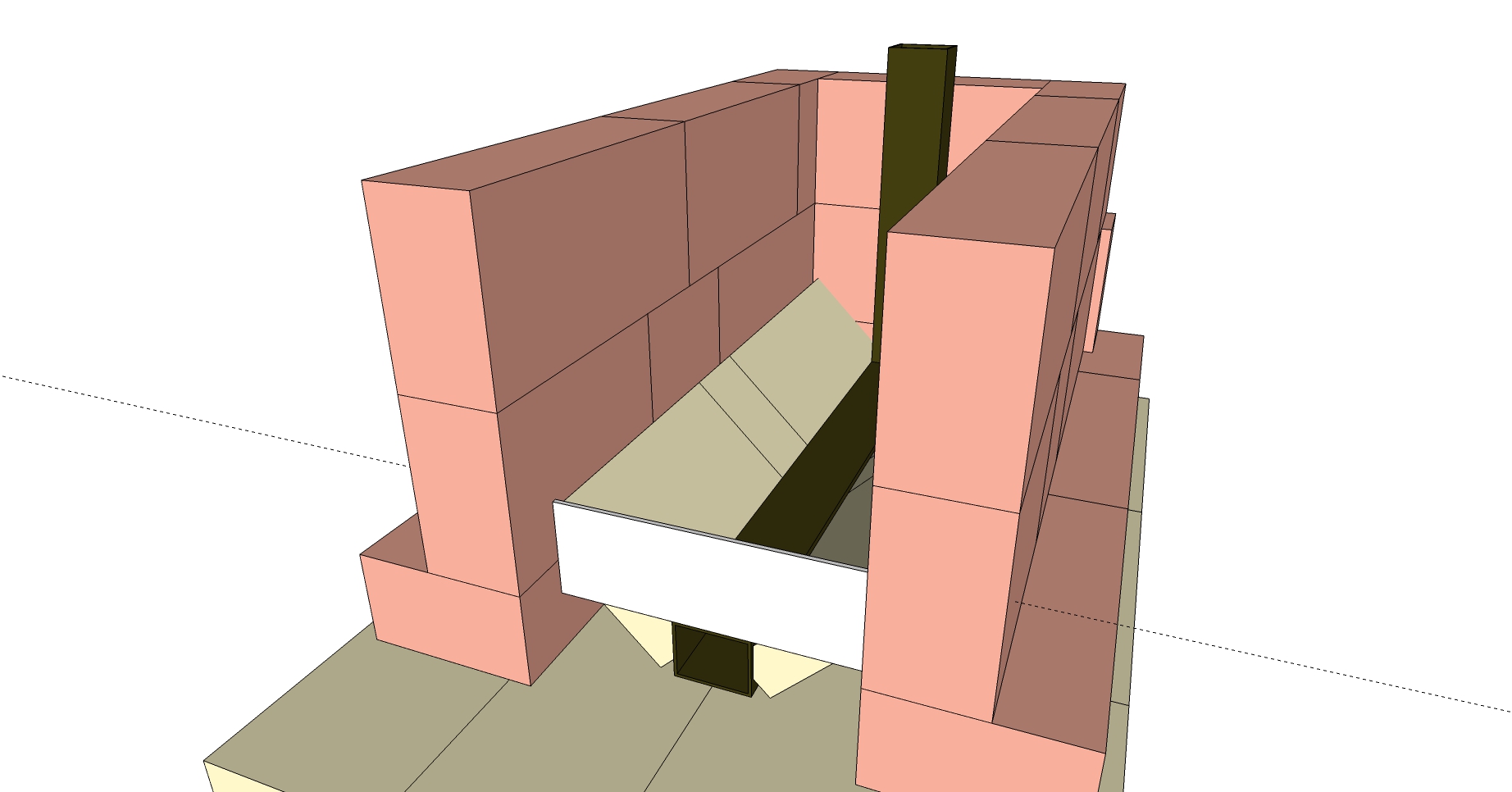 And a picture of the prototype doorstep in my own heater. 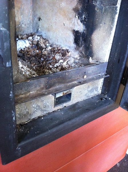 |
|
|
|
Post by smarty on Jul 2, 2018 13:06:21 GMT -8
|
|
|
|
Post by peterberg on Jul 3, 2018 1:20:14 GMT -8
Correct, bar one detail: the 70 mm is on top of the floor channel.
|
|
|
|
Post by smarty on Jul 5, 2018 8:42:17 GMT -8
Well I got as far as testing the thing I’ve made and I must have got something wrong because it smoked like billy-o!
I haven’t got any 6” stove pipe so I used a 2m length of 7” instead and it’s just pushed into the unsealed hole in the brick box that surrounds the thing as shown in the Abbey sketchup drawing. I’m wondering if I should have a direct connection to the outlet in the top tunnel? Then a means of opening it up to go to the bench outlet once it’s going. At the moment the exhaust goes into a brick chamber beneath the stove and I’ve blocked off the bench outlet down there. This is where I thought the bench bypass would go but I’m wondering if it should be in a flue pipe linked directly to the top tunnel outlet?
Is it the temporary 7” pipe with not airtight joints? All the inner dimensions are as shown in the sketchup drawing. I can’t be far off getting it to work but the smoke is bad.
The wood was dry and well seasoned. Any ideas anyone?
|
|
|
|
Post by peterberg on Jul 5, 2018 12:52:43 GMT -8
Frankly, I am in the dark here. have you tried the whole of the build or just a mock-up outside?
|
|


