|
|
Post by peterberg on Oct 24, 2017 0:36:35 GMT -8
During the Innovators Event, I've built a mockup of a new core idea. Based on my experience with the earlier 45 degrees riser and the findings of Brian Livelsberger, also known as DCish on this board. His experiment proved the double vortex could be formed in a number of directions, 45 degrees up being not the only one. Of course I tried this at home beforehand and the results were encouraging. 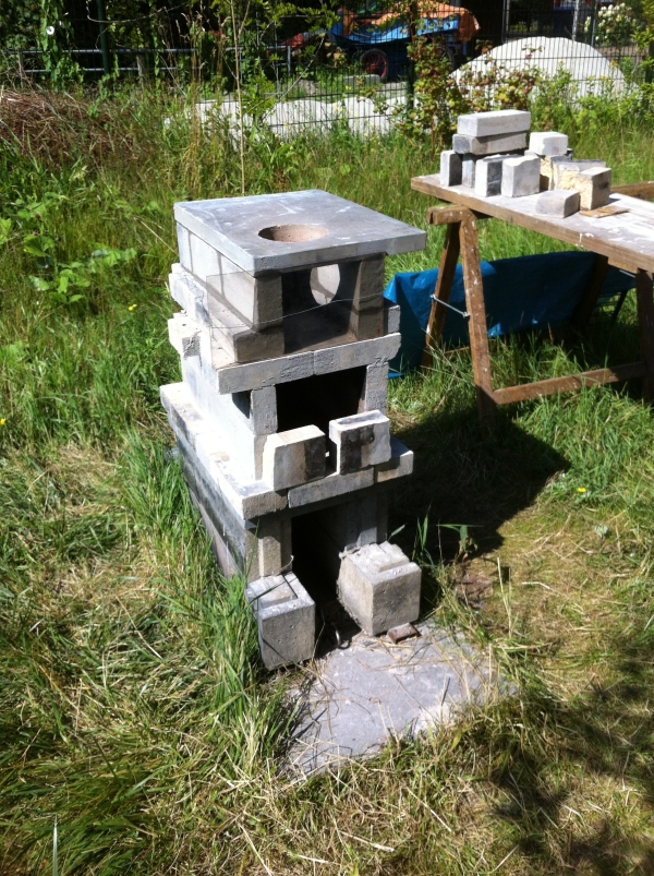 I've made half a dozen videos of it and uploaded two to YouTube, here they are. The second one seemed to be the better option although the double vortex looked much more chaotic. It was more like a fire fountain with smaller vortexes at the side and the end of the flames, dancing around all the time. This is much better visable in the next video, taken from the actual mockup build in Montana. This is done using insulative firebricks and sporting a very short chimney. In fact, this is the second version built at that location. It sports a glass top and glass front, both the inside of the firebox and fire tunnel are visable. I hope you don't mind the sound track, it was too funny to replace it by a piece of music. More about this later in the day. |
|
|
|
Post by Jura on Oct 24, 2017 1:12:59 GMT -8
May I presume the flue gases were Testo tested ? :-)
If so what is the results' comparison to the "standard" (ie. vertical riser) batch box?
|
|
|
|
Post by peterberg on Oct 24, 2017 5:37:38 GMT -8
Yes, the flue gases were tested using a Testo gas analizer. The results are a bit strange and not very consistent yet, in that the CO remains quite high (average 1165 ppm at best) but the white probe filters are dingy instead of the usual black. This was done with a very simple floor channel in a smaller cast version inside my workshop. 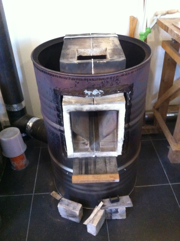 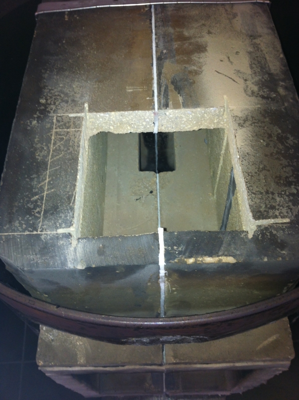 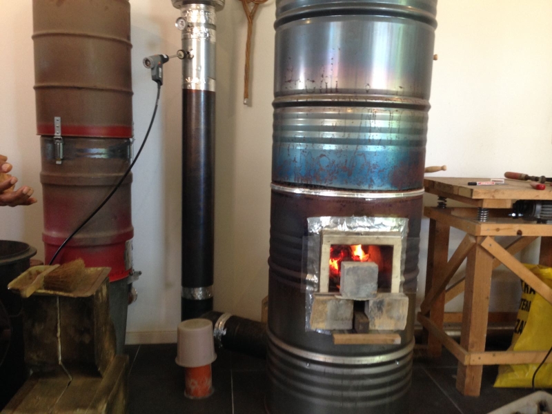 |
|
|
|
Post by peterberg on Oct 24, 2017 6:47:29 GMT -8
|
|
|
|
Post by peterberg on Oct 24, 2017 8:11:20 GMT -8
The goal was and still is a burn that's as clean as possible. Another goal was to create the possibility of cooking on top so it would be easier to create a kitchen range around it. Whether or not the temperature is lower and by how much is something to be found out.
|
|
Ralf
New Member

Posts: 42 
|
Post by Ralf on Oct 24, 2017 10:38:27 GMT -8
Hi Peter,
I followed a video of your talk at the RMH Jamboree and you said the CO is the last compound of the combustible gases to burn. Maybe there´s not enough time for the final burn of CO because the speed in an "updraft" condition like this is too high (only guessing) ?
In your first post you liked the second version better, what is the difference, secondary air supply ?
I guess since the ceiling is gettig so hot embedding a cannel for the secondary air there would work fine, or is that thought misleading ?
And finally: is this batch lit at the top to start it ?
Big big thanks for your generosity to share all this wonderful findings with everyone !
|
|
|
|
Post by peterberg on Oct 24, 2017 11:49:37 GMT -8
I followed a video of your talk at the RMH Jamboree and you said the CO is the last compound of the combustible gases to burn. Maybe there´s not enough time for the final burn of CO because the speed in an "updraft" condition like this is too high (only guessing) ? Your guess is probably right, an upcoming design for a kitchen range is coming a long way to solve this by making a U-turn in the tunnel so it's longer and can get down to a bench or up to the chimney. In your first post you liked the second version better, what is the difference, secondary air supply ? The second video showed the one generating the best results, that's all. The highly chaotic fire fountain is probably best to burn combustibles in this situation. I guess since the ceiling is gettig so hot embedding a cannel for the secondary air there would work fine, or is that thought misleading ? I started with a tube at the ceiling of the firebox, injecting air in the nearest end of the port. But now it's a tube at the bottom of the firebox, going vertical at the back and ending halfway in the port depth. This one is yielding much better results so far. And finally: is this batch lit at the top to start it ? Yes, it is. The earlier the flames are rising up through the port the sooner it runs smokeless. |
|
|
|
Post by maulionc on Oct 25, 2017 0:12:46 GMT -8
Hello péter
Do you have already the dimension of your new design ? The output power ? And efficiency ?
Charles
|
|
|
|
Post by peterberg on Oct 25, 2017 1:34:14 GMT -8
Hi Charles, welcome to the boards.
Too early for output and efficiency numbers, those are six months away at least. The whole thing is very new, just the materialization of a couple of ideas.
I'll do an evaluation of the dimensions and post those today, ice and weather permitting.
|
|
|
|
Post by peterberg on Oct 25, 2017 9:06:25 GMT -8
I recreated the drawing of the double shoebox mockup with glass on top, the videos of Attilio were a great help with that. The dimensions are as follows, measured in millimeters: Firebox 511 deep, 294 high and 200 wide. Tunnel 460 deep, 170 wide and 180 high. Port 176 deep, 64 wide. Floor channel 50x38x2.5, ending halfway in the depth of the port. The original at home did use a 60x40x2 tube as the floor channel. 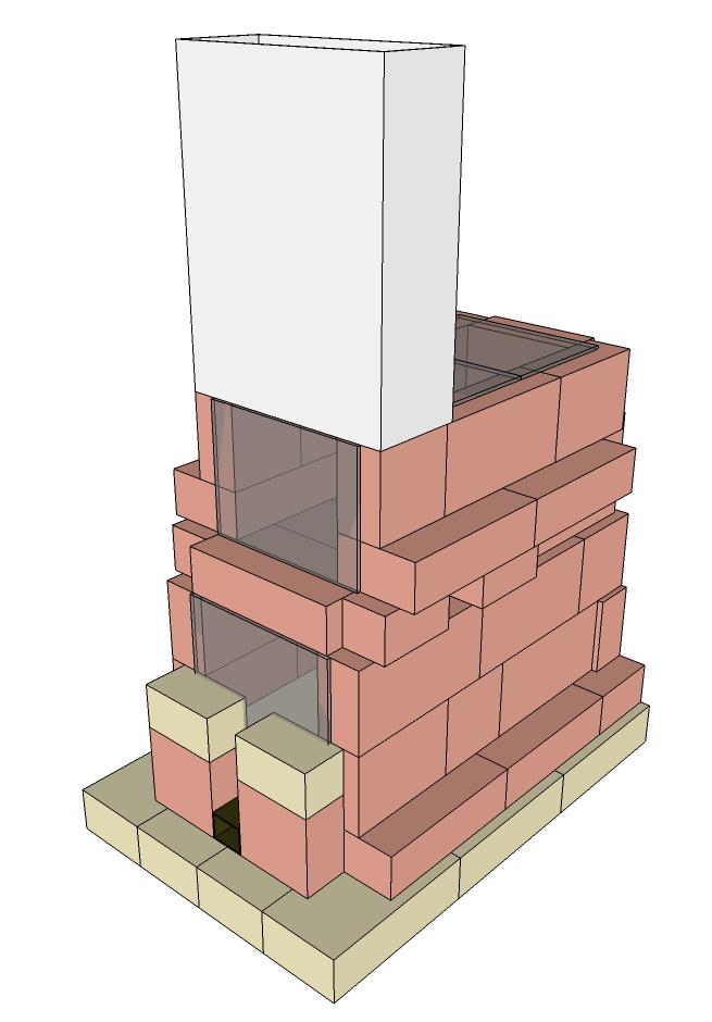 I have to stress that most of the dimensions are dictated by the size of the fire bricks, so when you intend to build the thing out of other bricks just use the pattern of the bricks as laid out in the SketchUp drawing which is available here. All the dimensions are nominal, without calculating the seams. In case conversion of the dimensions to imperial is called for, here's a very comprehensive converter. Air inlets used for this mockup were approximately 20% for primary air and 10% for secondary air when viewed as relative to a 150 mm (6") chimney pipe. When the whole of the core gets hot the primary air could be reduced to 10% so the air inlet proportion would be 1 to 1. |
|
|
|
Post by Karl L on Oct 25, 2017 14:15:16 GMT -8
Hi Peter,
Can you post the Sketchup file for that, so I can understand the details of the secondary air arrangement?
|
|
kpl
New Member
Posts: 47
|
Post by kpl on Oct 25, 2017 21:24:47 GMT -8
In this kind of setup, would it be wise to put secondary air channel above the ceiling, "on the second floor" - could the metal tube live longer with less oxygen available? Small door above the firebox door would allow easy replacement too.
|
|
|
|
Post by Jura on Oct 25, 2017 23:39:59 GMT -8
Hi Peter, Can you post the Sketchup file for that, so I can understand the details of the secondary air arrangement? But Peter has posted the link to the sketchup file in the post you answered to. The P-channel ends in the middle of the firebox ceiling |
|
|
|
Post by Karl L on Oct 25, 2017 23:44:44 GMT -8
Thanks - and sorry for not noticing!
|
|
|
|
Post by peterberg on Oct 26, 2017 0:16:14 GMT -8
In this kind of setup, would it be wise to put secondary air channel above the ceiling, "on the second floor" - could the metal tube live longer with less oxygen available? Small door above the firebox door would allow easy replacement too. I've found out the best place to feed secondary air in is at the back of the port/tunnel in this setup. The vertical part of the floor channel in the firebox is needed to heat the air sufficiently and the best spot to end is halfway in the port where the underpressure is strongest. To answer the question directly: placing the channel in the tunnel would be a second rate solution in my opinion. |
|


