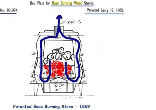
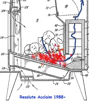
Sorry, I was a bit busy...
I add the beginning of the text of the patent for the Resolute Acclaim stove, from Vermont Castings which has some interest because it summarize up the problems to be solved in a stove and the ways which were found till now :
"1. FIELD OF THE INVENTION
This invention relates generally to solid fuel stoves, and more particularly to wood burning stoves provided with secondary combustion means for reducing the levels of polluting emissions while maintaining a high level of heating efficiency.
2. BACKGROUND OF THE INVENTION
In recent years, wood and coal burning stoves have gained widespread popularity for home heating. These stoves operate efficiently and for long periods of time in a slow combustion mode. The joints of such stoves are tightly sealed and air flow into the stove is carefully controlled. Such slow burning stoves operate very efficiently, but are subject to soot and creosote build-up in the stove itself, as well as in the chimney or stovepipe. In addition, as wood is burned, products of both complete and incomplete combustion are created which contain polluting emissions, including particulate material and unburned volatiles, and which are discharged into the atmosphere. This problem is exacerbated when burning at low heat levels in an oxygen-starved mode. Creosote build-up is dangerous because it can ignite, causing a hazardous chimney fire. The particulate emissions and the unburned volatiles are damaging to the environment. Furthermore, the heating value of the unburned volatiles is wasted, as they are discharged into the atmosphere.
Various techniques are presently used to remove the creosote and particulate emissions, as well as to burn the volatiles, to provide a cleaner burning stove having a high thermal efficiency. One known apparatus is a catalytic combustor or converter, such as that disclosed in US Pat. No. 4,646,712, assigned to the assignee of the present application. Such known catalytic combustors usually include a thick, perforate honeycomb structure of ceramic or other material coated with a catalyst material such as platinum, paladium, or rhodium. The surface properties of these catalyst materials are such that the combustion products, too cool to burn unaided, will burn within the catalytic combustor.
Many manufacturers have introduced retrofit units for existing stoves which include catalytic combustors for reducing the levels of smoke and creosote and for increasing efficiency. The operation of many of such known retrofit units is unpredictable at best, and depends substantially upon the base appliance to which it is attached. A marginal situation in many prior art retrofit units is caused by locating the retrofit catalytic combustor too far from the wood stove fire box. This location causes the exhaust gases entering the catalyst to have a temperature which is too low for optimum catalyst performance, particularly when the stove is operated at lower heat output levels. A retrofit unit which overcomes many of the problems associated with other prior art retrofit units is described in US Pat. No. 4,646,712, assigned to the assignee of the present application.
Wood burning stoves are also known which employ a secondary combustion system without a catalytic combustor for further burning of gases from the primary combustion chamber. In many such non-catalytic combustor designs, multiple primary and secondary air introduction systems are used. Frequently, horizontal baffles are employed which project across the top of the fire box, dividing the fire box into primary and secondary combustion zones. The lower half of the fire box is generally surrounded with refractory fire brick or insulation. Such prior art designs are dependent upon heat produced and contained in the fire box to promote the secondary combustion of remaining unburned pollutants above the baffle, and they work best primarily at higher fuel combustion rates.
Generally, such wood burning stoves with secondary combustion systems, even if they are capable of sustaining combustion prior to a log shift, may "wink out" during a change in the exhaust gas composition due to a shift in the fuel load, caused, for example, by a falling log. Even if the exhaust gas composition is restored shortly after the disturbing event, the secondary system may not reignite if it has cooled down sufficiently in the meantime. The reason for this "wink out" phenomenon is that to maintain secondary combustion in a clean burn mode in a stove with a conventional secondary combustion system, the combination of sensible heat (the heat contained within the gases before they enter the secondary system) and latent heat (the heat released when the combustible constituents of the gases are burned in a secondary system) present in the gas mixture must be sufficiently high to continuously maintain temperatures in the secondary system of about 1000-1200° F. If the gas mixture changes temporarily so that the total amount of heat (sensible and latent) available to the secondary system is insufficient to maintain the proper temperature, secondary combustion will cease. The gases will not reignite, no matter how rich, until they are again brought up to a temperature of 1000-1200° F. when entering the secondary system. In general, reignition requires attention from the operator similar to that required during the initial lighting of the secondary system. Operation of a stove with a secondary combustion system when the secondary combustion is extinguished is to be avoided, since the resulting creosote and other emissions typically will equal those in a conventional wood stove having no secondary system.
Another problem found in association with conventional secondary combustion systems is that they do not function at low burn rates in which the heat output from the primary combustion chamber is lower. It is these low burn rates which are generally employed by the public in wood burning stoves and which are the primary focus of most governmental regulations. During such low burn rate operations in many prior art systems, the gases exiting the primary combustion chamber are often at too low a temperature to sustain ignition in the secondary combustion system.
It is therefore a general object of this invention to provide a clean burning solid fuel heating apparatus having a high thermal efficiency.
It is another object of the present invention to provide an efficient solid fuel heating stove having an integral secondary combustion package for removal of creosote, particulate emissions, and unburned volatiles prior to release of the exhaust gases to the atmosphere.
It is a further object of the present invention to provide a wood burning stove which meets or exceeds all government regulations relating to emission levels for gaseous and particulate constituents, and which has a high level of thermal efficiency.
It is yet a further object of the present invention to provide an efficient wood burning stove having a non-catalytic design for removal of particulate material, unburned volatiles, and creosote and which is capable of sustaining its performance over a range from very low burn rates to very high burn rates.
It is yet another further object of the present invention to provide an efficient wood burning stove having non-catalytic design for removal of particulate material, unburned volatiles, and creosote which will continue to remove such gaseous and particulate materials, regardless of momentary changes in the exhaust gas constituents.
SUMMARY OF THE INVENTION
According to the present invention, these and other objects and advantages are achieved in a heating apparatus for burning solid fuels comprising a primary combustion chamber, and an internal, secondary combustion package in which a constant but specific amount of secondary combustion air is mixed with and aids in the combustion of unburned pollutants. The secondary combustion package does not utilize a catalytic combustor, but rather relies upon heat generated in the primary combustion chamber, in combination with heat produced by secondary combustion within the secondary combustion package, to sustain the secondary combustion for removal of the unburned pollutants.
In one aspect of the invention, the entrance orifice to the secondary combustion package is disposed at a low point on the fireback in the primary combustion chamber, which is a natural collection area for the charcoal formed during the combustion process. A sloping bottom grate is provided to enhance the accumulation of charcoal against the rear of the fireback. The combination of the sloping grate, which slopes downwardly toward the entrance orifice, and the location of the orifice, causes the entrance orifice to be covered by charcoal formed by the combustion process under normal operating conditions. As a consequence, the exhaust gases are forced to pass through the charcoal prior to their entrance into the secondary combustion package. Unburned oxygen remaining in the exhaust gases reacts with the charcoal bed, raising the temperature of the exhaust gases to a temperature at which they will combust when mixed with secondary air. This feature permits combustion of the unburned pollutants even during operation at low burn rates. The process is self sustaining in any burn rate, so long as an adequate charcoal bed is established during the kindling phase, prior to adding the first main load, and provided that subsequent fuel loads are added while adequate charcoal remains covering the entrance orifice.
In another feature of the invention, the two primary combustion chamber sidewalls are full insulated from top to bottom. The use of this insulation increases the temperature within the combustion chamber which helps create an adequate amount of charcoal to keep the entrance orifice full, and which prevents a lowering of temperatures during low burn rates below acceptable limits for charcoal production. The insulation also maintains the primary combustion temperature at a higher level which reduces the temperature increase required while gases are passing through the charcoal bed. As a consequence, the overall system is less sensitive to small changes in parameters required to maintain and sustain secondary combustion.
In a further aspect of the invention, the secondary combustion package contains a plurality of generally vertical baffles having curved upper portions which are arranged and configured to reduce flow restrictions while promoting significant mixing of secondary air with the unburned pollutants. The secondary package is formed of a high temperature, low density refractory material which has a highly insulative quality for maintaining the elevated secondary combustion temperatures that are required. The secondary package also provides surfaces which reradiate heat generated during the secondary combustion process to help sustain elevated secondary combustion temperatures. A choke zone formed above the baffles forces the mixture of secondary air and pollutants through a single orifice, again promoting mixing between the unburned pollutants and secondary air and also concentrating the heat. The gases exiting from the secondary combustion package are directed through a channel which causes them to abruptly change direction, again promoting mixing.
In another, further aspect of the invention, means are provided for metering the secondary air into the secondary combustion package at its entrance orifice. In a preferred embodiment, a plurality of uniform diameter ports is evenly distributed across the orifice width. Air passes through an entrance hole in the outer skin of the stove, and into a plenum chamber which distributes the air evenly among the ports. This arrangement causes jets of gas which extend into the entrance orifice, permitting maximum mixing of the secondary air with the exhaust gases at the point where those gases are at their maximum temperature.
In another aspect of the invention, means are provided in association with the entrance hole into the plenum chamber for regulating the amount of secondary air introduced, depending on whether hard wood or soft wood is being burned.
The primary air introduction system includes a primary air inlet on the bottom of the stove, a bottom manifold, and two side manifolds disposed on opposite sides of the stove for conducting the air to a top manifold disposed along the top of the stove. Air is directed from the top manifold downwardly and uniformly over the interior surface of a transparent glass panel disposed on the front door of the stove.
A bypass damper is provided for bypassing the secondary combustion package to facilitate start-up until the requisite amount of charcoal has been formed.
The foregoing invention permits the removal of creosote, particulate material and unburned volatiles from the exhaust gases of a solid fuel stove which burns wood or coal or other solid fuels, while maintaining a high level of thermal efficiency, without using a catalytic combustor. This invention meets all present US Government regulations relating to emission standards for wood burning stoves. This invention also permits the maintenance of secondary combustion during and after composition and temperature changes in the exhaust gases is from the primary combustion chamber, due to shifts in the solid fuel load. Also, the foregoing invention permits the efficient removal of creosote, particulates and unburned volatiles from the exhaust gases over the entire range of burn rates, including even very low burn rates. "
--------------------------------------------------------------------
As I said, many patents were deposed to find downdraft solutions (without using, of course, any catalyst).
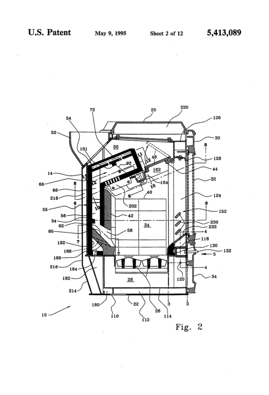
For example, in 1995 (patent 5413089), this secondary chamber with two intakes, up and down :
Before, in 1987 (patent 4677965), the flame was thrown down through holes in the ceiling :
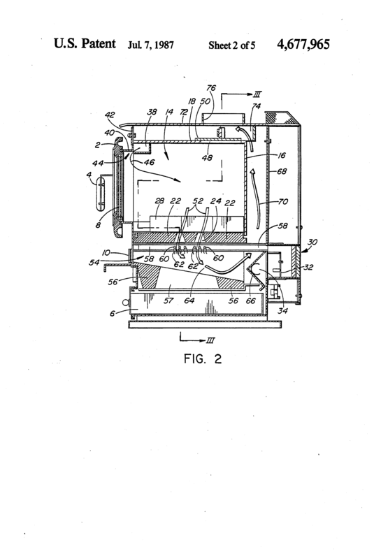
All those downdrafters were very complicated, as one can understand when looking at the numerous drawings in the patents! There were many parts (200 and more!), perforated and so on...Many pages and many figures in the patent to describe all those parts!
Everything got more simple with the two chambers one upon the other one :
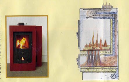
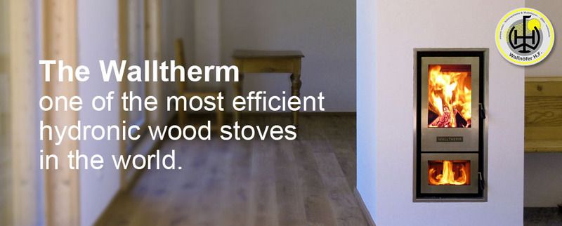
Notice the ram horns!
In 2001, this patent n°6213116B1 (more theorical than realistic) gave a so simple and clever design! Note the simple bypass at the top of the first chamber and the exit behind the stove, not being at the top!
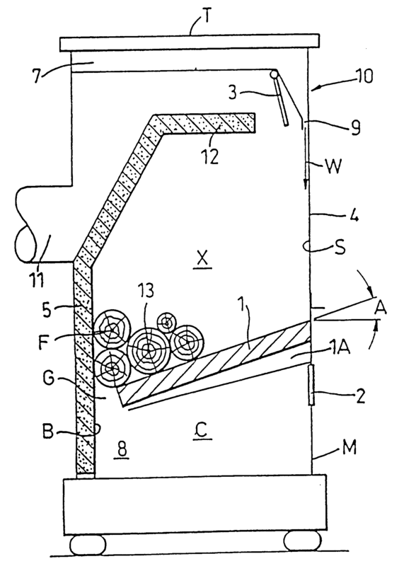
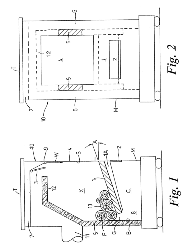
Xeeos Stove is, now, a good example of those new downdraft stoves, at 3000 euros!
I did not find patents on Xeeos, if somebody knows...
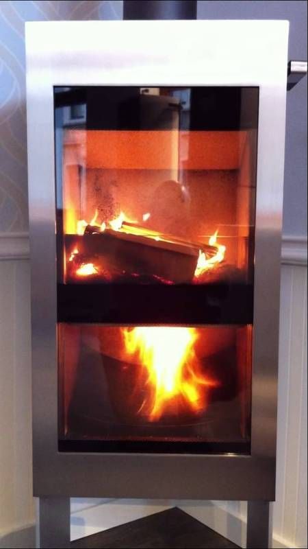
So simple!
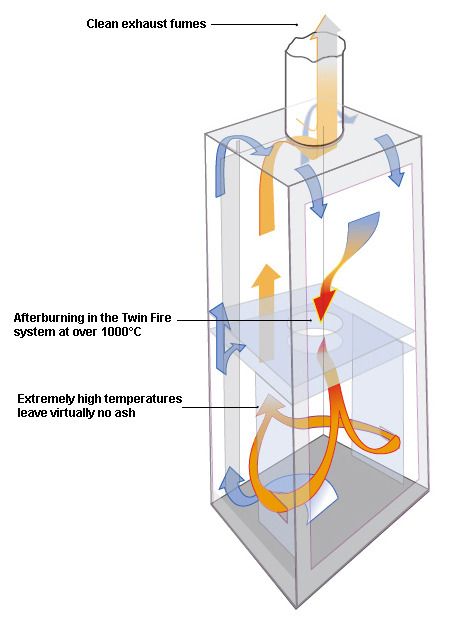
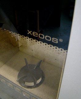
In Xeeos and Perry stoves, there is a kind of venturi or a mixer beetween both chambers where secondary air enters to mix with smoke.
In the wood stove "Perry", the entrance for oxygen is on the side but not directed towards the center to add more turbulence, more mixing :
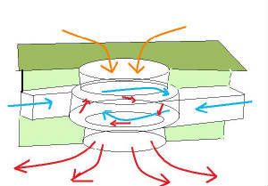
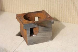
In the Xeeos, the air might be thrown to the center like a normal venturi :


One can also also see on this photo of the Xeeos stove that the second chamber is a bell where the hottest part is up and the cooler is down and so the exit :
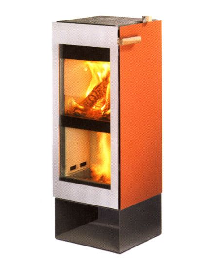
I add that I haven't built any downdrafter yet but I will soon as this kind of simple downdraft stove should be in the book that I am finishing writing (on easy metal stoves without inertie). I precise this because it would not be fair to hide this.
I wanted to add this stove in the second edition as I was almost ready but I am changing my mind...
I hope it gives many ideas and excites many brains as it did with me! Now, try to sleep!
Benoit
