|
|
Post by Donkey on Dec 7, 2009 9:15:25 GMT -8
Peter,
Re-reading this thread..
In your post of Nov. 2nd you wrote:
The chimney.. I think perhaps that in some instances the chimney should be reduced. I have at least noticed that in many cases it (at least) does no harm when chimneys are reduced after flue gasses have cooled off somewhat.
It seems to me that this could be a way to improve draft in a system that has used (almost) too much of the heat before the chimney.
I am wondering if you have noticed an improvement (or change in any case) in performance at any time with reduction of chimney size. ?? Say, after two (or three) bells, reduce, then what?
|
|
|
|
Post by peterberg on Dec 9, 2009 13:10:35 GMT -8
@donkey,
The chimney etc. story is a little bit different. The fire box is larger, the syphon is larger, but there it ends. The syphon is exiting into a bell (the first, not very large) and the exit of that one is equivalent to a 6" stovepipe. The rest of the contraption is also on a par with a 6" system. The setup at the moment is a triple bell.
I do think that's a bit different than smaller channels at the end of the smoke trajectory.
|
|
|
|
Post by Donkey on Dec 10, 2009 8:47:36 GMT -8
Heh.. Last night I asked a stupid question (without looking first). So this morning I went back and looked. Sure enough, you'd already answered it.
The heat riser (rocket siphon) is 4 inches by 8 inches. 32 square inches..
six inch pipe= 28.26 sq. in.
Then, you scaled up everything (except for the chimney) by 1.7 times..
The heat riser should then have a cross sectional area of 54.4 square inches.
Roughly, almost twice chimney size (a bit less).
Also, to be clear, the connection between the two bells is 28.26 sq. in. or the same as 6 in. pipe.
Am I correct?
|
|
|
|
Post by peterberg on Dec 10, 2009 12:43:48 GMT -8
Recalculated the areas.
Old syphon has been 200 cm2 or 31 square inches. Syphon is 1.5 times larger than before. To be precise, 300 cm2 or 46.5 square inches. Ratio of 6" chimney pipe to new syphon is very close to 1.7, the afore mentioned scaling-up factor.
I do think this is about the highest ratio that would still be running well. Just to be safe, my choice would be no more than a ratio of 1.6.
Connection between bells is 195 cm2 or 30.2 inches. The chimney pipe is 177 cm2 or 27.4 square inches.
To sum up, syphon>connection>stack= 46.5>30.2>27.4 sq.in.
Conclusion: actually there is a stepping down, although not equal in percentages. The first step is 34% less, the second 9% less.
Something do seem to tell me it would be better to have equal proportioned stepping down. Say, like twice 23%. In that way the chimney draw would be better utilized.
One way to come to the right proportions is to scale down the syphon somewhat. And scale up the connection between the bells a little bit.......
For example, take a syphon of 44.3 sq.in. Two steps of 21.5% smaller do make for a ratio of syphon>connection>stack= 44.3>34.8>27.3 sq.in.
Thank you so much for the comment! I'll incorporate these results in the p.d. drawing. And it is an excellent example of my opinion about open source, without your thought the inconsistency would probably never have crossed my mind.
|
|
|
|
Post by Donkey on Dec 10, 2009 17:10:49 GMT -8
It seems to me that the optimum step down size between bells (or out to chimney) would be a function of how much heat is left over after each step. As the air contracts and becomes less dense, it would require a smaller diameter for the same throughput.
I'm curious, by which method have you chosen these reductions? They "feel" right to me, but I wonder at systematizing such choices.
It's my understanding that bells can be tuned for temperature. Narrower bells will be hotter (generally) and taller bells would hold a larger gradient, top to bottom. This is interesting to me as I've been thinking about how to make these stoves more versatile, doing more than one thing at a time, etc. I envision a system with multiple bells, each holding it's own temperature gradient, each doing a different job, oven, steam generation, water/ space heater, etc.
A key piece of this would be to know a couple (few?) of "rules of thumb".
One rule would be knowing the difference in temperature related to differences of bell size.
One rule would be knowing step down (or up) size related to heat differences, gain, loss, etc.
I'm sure there are more rules, though these come to mind instantly..
|
|
|
|
Post by peterberg on Dec 11, 2009 9:48:31 GMT -8
@donkey,
Alas, I'm not enjoying a science education. The only reasoning behind the choice for a percentage is this: The same happens to the heat transport through the stove. It decreases a certain percentage because of transfer to the walls etc. One observation I've made: the first bell is running much hotter than the second. Temp difference between second and third bell is much smaller. In order to distribute the heat better between all the bells, it looked like the step-down in size should be equal in some respect.
I am a trial and error developer, I would say.
|
|
|
|
Post by Donkey on Dec 11, 2009 11:56:45 GMT -8
Umm...
According to Kuznetsov, (all else being equal) a bell with a smaller top area (narrower) will be hotter than one with a larger one.
If what he says is true (it actually makes certain sense to me) then you may get better evenness (equality between the bells) of heat if you reduce bell size as you go.
So, assuming that you WANT the same temperature range throughout the system, you would need to make the first bell larger (not higher or taller, but wider and longer) and maybe the second and third would be made slightly smaller.
??
|
|
|
|
Post by peterberg on Dec 12, 2009 12:02:47 GMT -8
Errmm...
It could be done this way.
However, this theory won't apply to a single bell. Remember my first iteration? Being very high and narrow, the rocket made such turbulence inside that the heat distribution was excellent. The second one, being wider, had a hotter ceiling. Probably because of the same turbulence in a wider environment.
|
|
|
|
Post by Donkey on Dec 12, 2009 16:22:38 GMT -8
I was doing a little thinking and doodling last night. My results are along the lines of thought experiment. Just to be clear, there are no measurements math or observed fact behind it, though they should be accurate according to the theory.. Simply thinking out loud, trying so "see" what I've been reading and imagine results. The first image, is of 2 bells equally sized. Heat coming in from the left, going out towards the right. 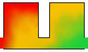 Next, what if the first bell is made smaller? Not shorter but narrower. 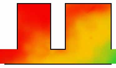 Then, how about making the second bell narrower? 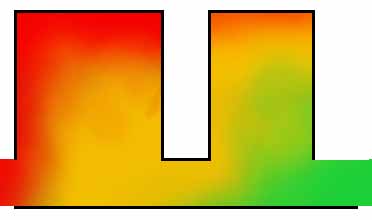 The first condition and the second act just as one would think.. The last acts a little non-intuitively. |
|
|
|
Post by endrunner on Dec 25, 2009 23:00:13 GMT -8
How did you decide the size of the fuel load box? Could it be any larger?
|
|
|
|
Post by peterberg on Dec 26, 2009 3:57:26 GMT -8
endrunnerWhen upscaling all the other aspects at the same time, the answer is a firm yes. The chimney is a mere 6" now, upstream channels inside the same. My method is very simple: change a single aspect and see how it works. When it stops working, that change need to be undone. In fact, I've been testing some slightly larger fireboxes.
|
|
|
|
Post by peterberg on Dec 26, 2009 8:22:35 GMT -8
First rocket/bell PD drawing is ready. 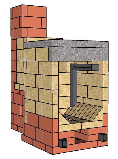 This one do contain all the results of development so far. I've decided to release in stages: the heart of the thing first, next with the first bell around it, etc. Of course the picture above isn't the drawing, that's just a jpeg image. The real 3D-picture is here: pberg0.home.xs4all.nl//pictures/PD/RB-PD1.skpThe format is Google's SketchUp, version 7, this is a free 3D drawing program. In order to view and manipulate the drawing, download the program here: sketchup.google.com/product/gsu.htmlThe drawing itself is organized in layers, every row of bricks forms one, more or less. It's perfectly possible to take it apart with the SketchUp tool "Move/copy". Select the tool, select a brick and move the layer away. In order to view all around it, press the scrollwheel or middle button and move the mouse. Once you're familiar with it, it's a great toy. About the stove: this one is more or less complete to build a bell around it. The firebox is there, and so is the syphon and the first upstream channel. Just in case anyone would like to build the thing with a single bell, please do omit the upstream channel. The bricks represent one with the dimensions 8"x4"x2". SketchUp do have a tool to check dimensions. |
|
|
|
Post by endrunner on Dec 27, 2009 12:00:01 GMT -8
Peterberg
I love your design and thank you very much for your efforts to publish the info. It helps alot. One of the reasons I became interested in rocket stoves was their ability to reach high heat. I am looking for a way to burn glycerine, but it requires north of 1000 degrees. The less efficent rocket stoves are below this. The other aspect of this is I have been researching thermal driven air conditioning. I am wanting to use zeolites in an adsorption process.
So I have a couple of other questions if you have a moment. 1st to burn the glycerine do you think I would need a second combustion chamber for the glycerine burner that starts at the top of the heat riser in order to have the high temperatures, or would the top of the main wood combustion chamber be hot enough?
2nd rather than have a large bell for heat radiation I was wanting to install heat exchangers or perhaps heat pipes to drive the AC load. Do you have any thoughts in this regard?
thanks
|
|
|
|
Post by peterberg on Dec 28, 2009 2:29:08 GMT -8
endrunnerThis design has one specific target: to burn wood efficiently. Presuming the glycerine is in a liquid form, I'd think the burn tunnel i.e. the deepest spot of the syphon would be the hottest. Injecting the liquid somewhere in that region ought to be the most effective way. In order to work, the syphon should be heated up first. About heat exchangers other than ceramic, my knowledge is very limited.
|
|
|
|
Post by peterberg on Dec 28, 2009 5:33:06 GMT -8
During this week the updates will following close behind each other... This update can be found here: pberg0.home.xs4all.nl//pictures/PD/RB-PD1a.skp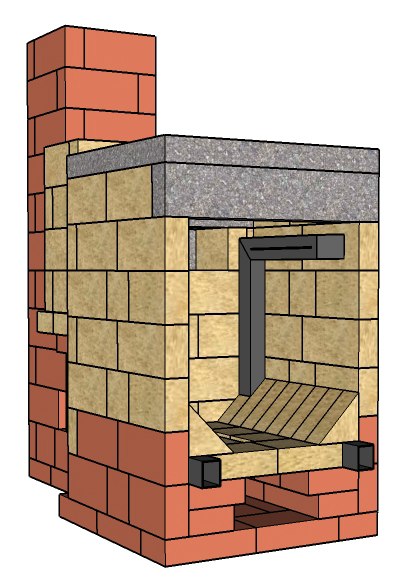 The lowest region has been changed: the horizontal side-airducts are repositioned 4" higher up. Consequently, they will be closer to the fire and warm up quick. The floor of the firebox do consist of replaceable firebricks. To this end, they are not glued together in any way. So, it's possible to replace the airducts without dismantling the stove in its entirety. |
|