|
|
Post by chrisburge on Jan 18, 2013 10:11:02 GMT -8
There have been a lot of individuals that have expressed interest in a sub-6" system. Either for space concerns, heat output/BTU, or portability.
I think that such a system can be made to work. I know that there are concerns with such issues as draft velocity, laminar restriction, gas friction, etc. Plus, at what point does the idea of down-scaling the principles of an RMH become a moot venture simply because the reduced output of a smaller system would take longer to 'charge' a thermal battery anyway, thereby requiring the same amount of fuel as a slightly larger system.
Bearing all of this in mind, I still think that such a system has merit and that a lot of these perceived limitations could be designed and tinkered out.
I think the first place to start is to re-think the format a bit. Rather than trying to simply design a smaller version of the 55-gallon, two-ton mass, cobbed-in bench style system, the 4" RMH is going to need a different approach-- one that accommodates for the smaller system's shortcomings by reducing its limitations yet still create a robust system that could effectively heat a <500sq.ft. area, maybe slightly larger.
I've been banging this whole concept around in my head for months now... I've gone through good ideas, bad ideas, different sketches, possible solutions, possible failures, built many little J-tube and L-tube stacks and risers in my back yard and fireplace, ranted on and on about Bernoulli, Heisenberg and Venturi to my eight-year-old while driving him to school... and after all of that, I think I have something worth kicking around the table. I finally took the time to put something together in SketchUp so that I can throw it out here and see if it floats  . .
So far, this project still seems feasible, and I've amassed almost all of the necessary materials, so the first phases of construction are not far off, but I think open discussion is in order before that takes place. Of course, I will document all of the construction here as this moves forward.
In my experimentation with burning in small draft systems, the major issue I noticed with all of them is ash build-up-- smaller CSAs become occluded quite easily. This convinced me that a smaller system is going to require a grate/ashpit of some kind and an effective ash collector.
I also noticed that it is quite easy to choke down a smaller system while trying to get enough fuel into the feed tube to achieve high temps and a good re-burn in the riser and that some type of draft control and/ or draft induction would be needed to ensure proper draft and maintain higher temps.
Now, the main case brought against a 4" system is that it doesn't have the oomph to drive a downdrafted exhaust through a horizontal bench mass to achieve the same efficiency as a typical 6" system. Well then, here's my solution: quit expecting too much from a 4" system-- decrease its mass load, decrease its horizontal run and give up a bit on the efficiency side of the equation. Look at it this way... if the typical answer to a small footprint/small space/lower output problem is a 'pocket rocket', which is much less efficient than an 'average' RMH (if there is such a thing:)), then there has to be some middle ground.
First off, let me say that I just got my hands on SketchUp, so I'm no master and some of the more subtle details are not hashed out in this model, but this is good enough to get the main ideas across.


I have a 16" x 22" steel civil defence issue water barrel that is the intended container for the project. Everything in the barrel will be cast inside of a mix of fireclay, alumina fibers, sharp sand, and perlite. I've test fired this material and it comes out light and hard. I have no real idea at this point what the final mass will be, but I'd be willing to shoot in the ballpark of <100lbs. The parts that are to be the feed tube, burn tunnel, coal pit, and lower part of the riser, will be made from a cardboard form that, after it is cast into the system, will be burned out before the actual heat riser is installed. The heat riser will be made of alumina/fireclay mache wrapped around a piece of sched.40 steel pipe that may, or may not, burn out, while everything else will be steel 4" duct. You can see that the feed tube and the burn tunnel have been rotated 45 degrees: this is so the system is somewhat self-cleaning. Ashes and embers fall into the coal pit where they are allowed to burn completely before sifting into the ash box which will have a removable drawer for easy cleaning during operation. There will be a cover of some kind on the ash drawer to control the bottom-draft. The radiant exchange will be a section of 8" single wall black stove pipe with an endcap. The exhaust chimney will be a 6' section of double-wall classB gas vent.
Here's a detail of the intended function:

Questions? Comments? WTFs? All are welcome.
|
|
|
|
Post by chrisburge on Jan 18, 2013 10:15:02 GMT -8
[There were some good questions asked on the other thread, so I thought I would post my answers here as well because they clear up a few details.] While that would give it longevity, and a bit more thermal transfer (although I think surface area would be quicker multiplier-- I've thought of using a piece of 10" stove pipe, but then I would have to have an offset riser and, it begins to get too close to the feed tube opening and, I would possibly have to incorporate a heat shield of some kind, which wouldn't be the end of the world), but I guess one of the running themes with this project is portability so, the lighter the better. Also, as I mentioned before, this is not what I would consider a refined rendering of the intended design-- I'm considering having the junction of the 8" pipe to the cast material be gasketed such that the stovepipe/endcap or both can be removed and replaced when necessary. The structural steel channel that is the ash box/grate for the coal pit, is also removable for replacment when it burns out. Yes. 3:1:1:9 -- fireclay:alumina fiber:sharp sand:perlite Which? The squeejaw way the elbow exits the barrel? As far as the angle at which the elbow exits, once again, not a perfect drawing. For the most part, it's proportionally correct, but not what I would call positionally correct. Things like... ...the ductwork on the bottom (which I might do with 4" flexible exhaust tubing, the automotive kind, instead of 4 elbows-- not only for a smoother path for the gases, but to be able to line up with the side of the barrel exactly and not have to cut some eccentric opening. I will probably also use a more serviceable joint at the exit of the barrel-- like a class B snap-loc), ...or the way the gases transition from the bottom of the upper "barrel" into the ducting through the lower barrel (this will be much less clumsy than it appears as I will be cutting and bending a 10"x4" 'register box' to create a much better junction), ...or the distance to which the stove pipe "barrel" extends into the cast material (this will be much shorter) ...or the way the feed tube has the just slightest taper towards the opening (this is just the way SketchUp warped the tube when I 'rotated' the end to get the bias-- I'm sure there is a much better way to do this, but it was the intuitive solution at the time. In reality, I'm actually considering making the feed tube portion of the form be shaped on top of a firebrick split so that the opening will have a flat bottom and a round top, kinda like a train tunnel. This will not only give the feed tube greater durability, it will be a better flow transition at the coal pit) ...all of these things need to be hashed out in a new drawing. As before: this is just to get the initial idea across...I'll be posting a revision soon. Or the T-junction? (which is what I think you are referring to) The tee will have an endcap on the bottom and is intended as a fly-ash/condensate catcher and clean-out. That's actually an excellent idea to add to this design and I already have visions of cutting aluminium channel dancing through my head. I'm gonna have to find somebody with a drill press and a bandsaw that I can use... While that is entirely possible, since I do have two of these old CD water barrels, and each one has a nice recessed lip on the bottom that fits perfectly into the lid of the other for easy stacking...I promised the person that gave me these that if the first stove works, I would make him a second one in the other barrel. I mean, these are pretty cool. They both still have the complete paint-stamped "Civil Defense Department" instructions on the side for how to use it to store and dispense drinking water...or use it as a commode ;P The real cherry-on-the-cake subtle irony with these is that they were manufactured by Rheem!  True! While scrounging at a local place that has a lot of smaller sized steel barrels, I did see a malt syrup barrel that was the 14"x35" size (22gal?) ...tall and narrow... it would be a bit of a squeeze at the top with a 'V-tube' style rocket, but it might work. ...oh, I'm gonna be spending a lot of time on SketchUp... I have, and I would have to say that that there are a few other similar 'radiant bell, no mass' designs that I have seen, but another critical point to this project is to have a self-contained, radiant-mass system that will still deliver heat after the fire has gone out. The other plus to this design is give the unit a better 'safety zone' by essentially having the stove be the mass and giving it a slower dissipation rate. It remains to be seen what kind of burn time/heat retention/hot spot dynamics it will have...it may be a smaller system, but I do expect it to burn quite nicely. ...and, not to be a broken record, but: portability. |
|
stino
New Member

Posts: 1
|
Post by stino on Jan 19, 2013 9:26:49 GMT -8
I like the looks of where this is going and am looking forward to seeing it materialise. I'm very much a beginner at this but first impression is that the gap between the riser and barrel is very narrow, will this not create a high temp. hot spot making the barrel last a lot less long? Why not create a a bigger gap and make the barrel (a lot) higher.
|
|
|
|
Post by chrisburge on Jan 19, 2013 17:05:51 GMT -8
first impression is that the gap between the riser and barrel is very narrow, will this not create a high temp. hot spot making the barrel last a lot less long? Why not create a a bigger gap and make the barrel (a lot) higher. The gap at the top has to fall into a very specific range to maximize the draw on the system from the difference engine that the radiant exchange creates. It's best that the gap at the top have a CSA that is the same as the riser. In this case, a 4" diameter circle happens to have a CSA with the same value(2^2*3.14= 12.567^2) as the diameter (4*3.14= 12.567), so a 1" gap is what is shown. Plus, as the gases travel outward across the top of the "barrel", the CSA only gets larger. By the time they've reached the edge of the insulation where they begin to fall downward, they've only travelled one inch, but the CSA in which they are travelling has more than doubled (3^2*3.14=28.26^2!) |
|
|
|
Post by peterberg on Jan 20, 2013 2:18:12 GMT -8
Chris, In my experience, there are a couple of flaws in your design. Some are serious, hampering the sought-after clean burn of the rocket mass heater. Others are a nuisance in daily use, or requiring a complete rebuild in one season. So, in no particular order: Clean burning inside a rocket stove will only occur when utilizing a short horizontal tunnel. Therefore, this 45 degree tilt of tunnel and feed will kill off the best feature of the stove. Having both downdraft in the feed and updraft via a grid isn't going to work. Almost certainly, during a burn the fire will creep up into the feed and stops the downdraft all together. This 45 degree feed, I'm not convinced it would work satisfactorily. I've tried it myself in a combination with a short horizontal tunnel and the setup isn't self feeding as good as the vertical feed. There's a sliding scale from horizontal (no self feed at all) to vertical (maximum self feed). When the hottest parts, feed, tunnel and lowest end of the riser are insulated, they will burn out quite quickly. This is not something to take lightly, it's almost guaranteed. When it won't burn out, the temperature won't be high enough to burn really clean. I do understand the smoke path is coming down via the "barrel" going up a short distance and down again via a convoluted path with several 90 degree bends to the chimney stack. This will cause a lot of friction, slowing down gas velocity and kill off the clean burn, if present. In my opinion, chances to a successful design would be insulation of the hottest parts individually, leaving space around the parts to create a downdraft through the whole water barrel to a single outlet close to the floor. In order to avoid clogging up of the ashes, at least for a part, you could round the junction of the corner where the tunnel floor and the riser meet. Having an ash pit in combination with a drawer would be enough to tackle the ash difficulties. See my thread about Small scale development for more information about the matter. It would be wise to implement a p-channel and trip wire as well. The benefits of these add-ons are tried and proven by now. My opinions are my own, everybody is free to think otherwise. |
|
|
|
Post by chrisburge on Jan 21, 2013 12:31:07 GMT -8
Peter, I'm going to have to respectfully beg to differ with a lot of what you have said... Clean burning inside a rocket stove will only occur when utilizing a short horizontal tunnel. Therefore, this 45 degree tilt of tunnel and feed will kill off the best feature of the stove. First of all, If you'll recall what I stated at the beginning of this thread, I think that a 4" inch system might have to live up to a different set of expectations. It is a given that this design is going to have to sacrifice a certain amount of performance to gain a certain amount of portability. Also, to candy-coat it, I would consider this initial drawing to be somewhat crude. Some design changes and a cleaner drawing are forthcoming... That being said, I think that this configuration will have a relatively clean burn, maybe not an absolutely clean burn, but a clean burn nonetheless. I find it hard to agree with such a finality, that a 'clean' burn can only occur in the presence of horizontal tunnel, when there are plenty of examples of remarkably clean-burning rocket stoves and heaters with an L-tube instead of a J -- wherein the fire only burns at the bottom of the riser. Au contraire mon frere... (pardon the video quality) Amongst other things, I built this little test stove to prove that such a configuration could, and does, work. Not only will this little system burn pallet slats and pellets at the same time for hours on end without a single hiccup (so far, the best fuel combo), but it will also happily burn load after load of oak 2"x4"s-- two, 2' sections at a time  ...without ever smoking or flaming back. The only way to make it smoke back is to let the pellet feeder run out. When this happens, the front of the feed box will still draft downwards while the last of the pellets gasify and eventually ignite before they burn down far enough so that the top of the pile is below the top edge of the hole at the bottom of the channel-- at which time, the draft will correct itself and pull the flames out of the bottom of the pellet feeder. During this brief period of time (only ~5 min), I close down the top of the feeder with a brick or a metal plate so that just 2mm of the front edge is open and all of the woodgas that is escaping is sucked down the front of the feeder and ignited in the burn tunnel-- looks like a smoke waterfall...very cool.  The key to the setup is the 45 degree vanes of the grill that direct the bottom draft forward into the feed tube. Here's a cutaway... 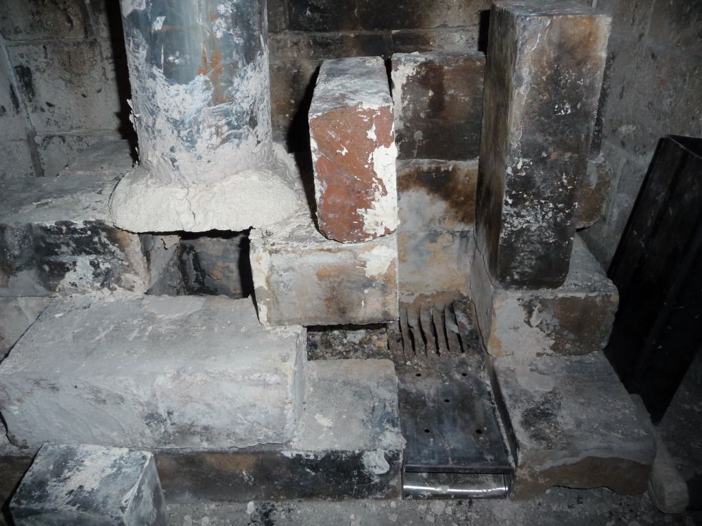 Notice how the bottom draft is so good that it winds up blowing more ash into the burn tunnel than catching in the ashbox. I would agree that 45 degree feed into a horizontal tunnel is guaranteed not to work because as the wood reaches the bottom, it has an additional friction coefficient to deal with. Plus, the obtuse angle of fuel delivery on a level burn surface merely pushes the fire apart and you lose the concentrated burn point. For this particular design, while it remains to be seen, I think it will perform just as well as a vertical feed... maybe even better. Once again, crude drawing, but as you can somewhat see, my intent is to not only have the wood meet the burn tunnel at a perpendicular angle, but the last 4" of 'bottom' of the angled feed tube is open space over the coal pit where the wood is only in contact with the bottom of the burn tunnel. This will allow the coals to break off and fall below, with the fresh wood sliding into place over the coals. Drafting through the coal pit will ensure a complete burn of all the material and a tightly controlled burn point. This is definitely not something I am taking lightly. That is why I have tried to come up with a refractory conglomerate that is going to be able to handle the temperature and be a bit more resistant to thermal and structural stress. I've gotten the best results with adding alumina fibres to a mix of high-grade fire clay, silicon dioxide (sharp sand), and perlite. This will be incorporated with a lot of structural 'alumina mache' composed of ceramic wool saturated with fireclay slip. Also, since the highest temps needed to burn all the available gases is ~1200F, I don't see how burning out is necessary for burning clean-- burning out is just the nature of the beast. What is going to give you the cleanest burn is whether or not you have enough available oxygen present at those higher temps, and the only way to accomplish that is to increase the draft velocity and, subsequently, the amount of oxygen present in the system. Luckily, there are four things available in in such a system (and in most "rocket" burning technology) to increase the rate at which air is introduced into the system: the draft engine (riser); the difference engine (the radiant exchange or "barrel"); flow constriction ; and induction. Also, I am aware that the metal parts are likely to breakdown and spall and that's why I intend to make them replaceable. To this, I would say: my apologies, crude drawing, in the sense that a) the intended path is not to have it go up after leaving the "barrel" and then down, but simply to exit the bottom into a register box affair and continue downward; and b) while the intended smoother path through the bottom (which would be accomplished with a one-piece section of 4" flexible steel exhaust tubing) is not accurately portrayed through the hasty snatching of components from the engineering toolbox plugin, this will probably be changed in the next rendering to a simple 90; straight tubing; exit; tee-junction; chimney. While this configuration may also be feasible, it would be problematic for two reasons: 1) it would be a structural challenge to have the burn core be surrounded by airspace and 2) the intent of having an entire stove composed of a one-piece cast material is so that the stove becomes the mass and the heat dissipation rate through the surface of the water barrel is much slower than if it were reduced to just another radiant exchange. I have... lots of good work there. Carry on. I, however am not yet convinced that I need to throw the baby out with the bathwater . |
|
|
|
Post by peterberg on Jan 21, 2013 12:56:40 GMT -8
chris, Please, do build this stove and show us all an entirely new concept.
|
|
|
|
Post by angelo on Jan 18, 2015 13:14:37 GMT -8
There have been a lot of individuals that have expressed interest in a sub-6" system. Either for space concerns, heat output/BTU, or portability.
I think that such a system can be made to work. I know that there are concerns with such issues as draft velocity, laminar restriction, gas friction, etc. Plus, at what point does the idea of down-scaling the principles of an RMH become a moot venture simply because the reduced output of a smaller system would take longer to 'charge' a thermal battery anyway, thereby requiring the same amount of fuel as a slightly larger system.
Bearing all of this in mind, I still think that such a system has merit and that a lot of these perceived limitations could be designed and tinkered out.
I think the first place to start is to re-think the format a bit. Rather than trying to simply design a smaller version of the 55-gallon, two-ton mass, cobbed-in bench style system, the 4" RMH is going to need a different approach-- one that accommodates for the smaller system's shortcomings by reducing its limitations yet still create a robust system that could effectively heat a <500sq.ft. area, maybe slightly larger.
I've been banging this whole concept around in my head for months now... I've gone through good ideas, bad ideas, different sketches, possible solutions, possible failures, built many little J-tube and L-tube stacks and risers in my back yard and fireplace, ranted on and on about Bernoulli, Heisenberg and Venturi to my eight-year-old while driving him to school... and after all of that, I think I have something worth kicking around the table. I finally took the time to put something together in SketchUp so that I can throw it out here and see if it floats .
So far, this project still seems feasible, and I've amassed almost all of the necessary materials, so the first phases of construction are not far off, but I think open discussion is in order before that takes place. Of course, I will document all of the construction here as this moves forward.
In my experimentation with burning in small draft systems, the major issue I noticed with all of them is ash build-up-- smaller CSAs become occluded quite easily. This convinced me that a smaller system is going to require a grate/ashpit of some kind and an effective ash collector.
I also noticed that it is quite easy to choke down a smaller system while trying to get enough fuel into the feed tube to achieve high temps and a good re-burn in the riser and that some type of draft control and/ or draft induction would be needed to ensure proper draft and maintain higher temps.
Now, the main case brought against a 4" system is that it doesn't have the oomph to drive a downdrafted exhaust through a horizontal bench mass to achieve the same efficiency as a typical 6" system. Well then, here's my solution: quit expecting too much from a 4" system-- decrease its mass load, decrease its horizontal run and give up a bit on the efficiency side of the equation. Look at it this way... if the typical answer to a small footprint/small space/lower output problem is a 'pocket rocket', which is much less efficient than an 'average' RMH (if there is such a thing:)), then there has to be some middle ground.
First off, let me say that I just got my hands on SketchUp, so I'm no master and some of the more subtle details are not hashed out in this model, but this is good enough to get the main ideas across.
I have a 16" x 22" steel civil defence issue water barrel that is the intended container for the project. Everything in the barrel will be cast inside of a mix of fireclay, alumina fibers, sharp sand, and perlite. I've test fired this material and it comes out light and hard. I have no real idea at this point what the final mass will be, but I'd be willing to shoot in the ballpark of <100lbs. The parts that are to be the feed tube, burn tunnel, coal pit, and lower part of the riser, will be made from a cardboard form that, after it is cast into the system, will be burned out before the actual heat riser is installed. The heat riser will be made of alumina/fireclay mache wrapped around a piece of sched.40 steel pipe that may, or may not, burn out, while everything else will be steel 4" duct. You can see that the feed tube and the burn tunnel have been rotated 45 degrees: this is so the system is somewhat self-cleaning. Ashes and embers fall into the coal pit where they are allowed to burn completely before sifting into the ash box which will have a removable drawer for easy cleaning during operation. There will be a cover of some kind on the ash drawer to control the bottom-draft. The radiant exchange will be a section of 8" single wall black stove pipe with an endcap. The exhaust chimney will be a 6' section of double-wall classB gas vent.
Here's a detail of the intended function:
Questions? Comments? WTFs? All are welcome.
|
|
|
|
Post by Daryl on Jan 18, 2015 13:54:20 GMT -8
Not to piss anyone off but I think most of the small rocket designs are overkill for a tiny space. There is another thread where posters are including mass into a basic stove. Maybe that would be a better idea than overcomplicating the build. Vortex uses a very small footprint for his stove...and he can cook on it.
|
|
|
|
Post by peterberg on Jan 19, 2015 1:23:31 GMT -8
Angelo, welcome to the boards.
Above, you quoted the first post of chrisburge in its entirety. But without any comment, so it isn't clear what the purpose of your post is. Could you please enlighten us?
|
|
|
|
Post by angelo on Jan 19, 2015 11:44:59 GMT -8
Thanks Peter, I'm new to the forum, I saw that the design is quite content to make a good stove, just as you say to see where to correct for a good operation.
|
|
|
|
Post by harveymoo on Jan 22, 2015 14:16:48 GMT -8
I am not an expert by any means, but I like your design although I have a few suggestions. The tripple 90 degree elbows at the exhaust leading into the secondary clean out are kind of unnecessary and are just adding restriction to exhaust flow, I would just have one elbow going straight into the ash trap. Secondly I would fill the green barrel (not all the way) with a refractory insulation such as vermiculite, or clay and Perlite, to create a thermal mass. this will keep the feed tube and heat riser warm long after use and may make for less smokey back-draft coming out of the fuel chamber, when cold starting. |
|

 .
.


 ...without ever smoking or flaming back. The only way to make it smoke back is to let the pellet feeder run out. When this happens, the front of the feed box will still draft downwards while the last of the pellets gasify and eventually ignite before they burn down far enough so that the top of the pile is below the top edge of the hole at the bottom of the channel-- at which time, the draft will correct itself and pull the flames out of the bottom of the pellet feeder. During this brief period of time (only ~5 min), I close down the top of the feeder with a brick or a metal plate so that just 2mm of the front edge is open and all of the woodgas that is escaping is sucked down the front of the feeder and ignited in the burn tunnel-- looks like a smoke waterfall...very cool.
  The key to the setup is the 45 degree vanes of the grill that direct the bottom draft forward into the feed tube.

