|
|
Post by banung on Dec 5, 2023 13:14:15 GMT -8
Hello, about half a year ago I wanted to build batchrocket based rear loaded heating boiler. But the project was too complicated I almost canceled the project. Then I realised DSR3 model, which is much easier to implement to my project. So I started to design and then build with my friends. The key was too keep the project simple and use some on market available parts – doors. System is 150 mm internal tube diameter. The other parameters are possible to change simply by using different bricks. Water is entering on bottom on both sides of the heat exchangers and then entering the top L-shaped heat exchanger. (last picture - heat exchangers) Fumes – after leaving the tube* is expansion, fumes cool little bit and then go down through side heat exchangers and leave on bottom. There are openings for cleaning heat exchangers. In the top opening could be added small owen. * probably wrong, see next post 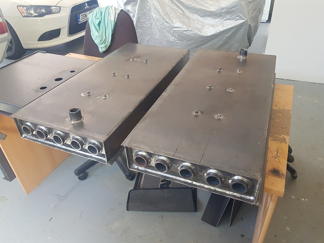       |
|
|
|
Post by banung on Dec 5, 2023 13:29:13 GMT -8
As I`m not able to open the shared SkechtUP file, I`m not sure with the right dimensions now. (And I don´t remmember where I got the dimmensions I used in my drawings.) So I have few questions:
*1) after fumes leaving the tube they should go back right above the tube? So my brick drawing is wrong, right?
2) the cross section area around the tube should be about 150 % of the inner tube cross section area? (grey areas on first drawing)
3) what is the chanell cross section area? (from fireplace to tube)
4) what is air inlet cross section area?
5) fireplace area is way bigger than it should be. But I will use only max. recommended weight of fuel. Big problem or not?
|
|
|
|
Post by peterberg on Dec 7, 2023 2:45:35 GMT -8
As I`m not able to open the shared SkechtUP file, I`m not sure with the right dimensions now. (And I don´t remmember where I got the dimmensions I used in my drawings.) So I have few questions: *1) after fumes leaving the tube they should go back right above the tube? So my brick drawing is wrong, right? I noticed that the drawing isn't right, yes. The exit opening should be at the back, not in the front. 2) the cross section area around the tube should be about 150 % of the inner tube cross section area? (grey areas on first drawing) It's yes, but it is the bare minimum. Better to aim for a bit more, 175% would do. The space above the tube is a factor as well, go for 40 mm at least. 3) what is the chanell cross section area? (from fireplace to tube) I am assuming you mean the port. This is 50% of chimney cross section area, proportions 1 to 4. 4) what is air inlet cross section area? This is a bit tricky: the initial opening in the front should be quite large, 50% of chimney csa, then it goes through the door posts, together 30% csa, the slits in the door posts and lintel together 50% csa again. This is all done in order to reduce friction, the air stream(s) will be changing direction several times. 5) fireplace area is way bigger than it should be. But I will use only max. recommended weight of fuel. Big problem or not? Yes, because the proximity of the port to the fire should be limited. My recommendation would be: stick to the numbers, then you'll know it will work as intended. The firebox could have a width and height that is equal, say 2.5B x 2.5B. Why can't you open the provided core drawing? Maybe it is saved in the wrong SketchUp file version? |
|
|
|
Post by banung on Dec 7, 2023 12:22:13 GMT -8
Why can't you open the provided core drawing? Maybe it is saved in the wrong SketchUp file version? Thaks very much for answers. Yes, the SketchUp file version is too new. I was able to open older files, but this not. If is it possible to save in some older version, it would be very helpful for me. |
|
|
|
Post by peterberg on Dec 7, 2023 13:08:33 GMT -8
If I remember correctly, I saved the file in SKP8 format. What is the version of SKP that you are using, is that older?
|
|
|
|
Post by banung on Dec 8, 2023 0:27:23 GMT -8
My father has version 6.4.247
Thanks Petr
|
|
|
|
Post by peterberg on Dec 8, 2023 7:41:02 GMT -8
|
|
|
|
Post by banung on Jan 8, 2024 12:48:33 GMT -8
Thanks wery much. I can open the file even in the Rino 3D, I´m using.
Today I made the firs test. Withnout water and bricks. Just testing the chimney and and trying to bake the paint.
|
|
|
|
Post by banung on Jan 9, 2024 3:08:20 GMT -8
So here are mi dimmensions, starting from the upper part of stoves. If I understand right, the general reference ara is about 177 cm2. (csa of the tube) On your drawing, there is only about 22 mm from top of the brick tube. If I add little bit of wool between the bricks I can have 40 mm or more. And the area will be about 320 cm2 (about 180 % of csa). So I think, this section is OK or maybe need some little tuning if necessary. 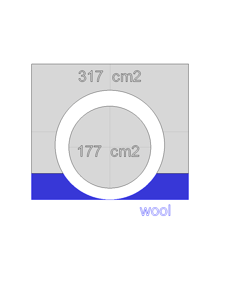 |
|
|
|
Post by banung on Jan 9, 2024 3:23:43 GMT -8
In your drawing the fireplace is 300 mm widht, 300 mm height and 400 mm depth. But the grate distance from the port is only 235 mm. There is also distance of the glass to the firebox and that is about 70 mm. At the end dimension of my fireplace is not that different. Widht and depth are the same. Height is 350 mm. I can add some bricks to the bottom. And/Or add some 45 deg cut bricks to the bottom and I also can add some grate. The lenght of the port is about 85 mm. Calculating bricks and wool. Dimension of the port is same as yours. The area of fireplace and tube is divided by steel, so there should be no fumes comming around. Distance of the glass from the fireplace is given by door construction and is about 140 mm. The good news is, that the door stayed clean all the time   |
|
|
|
Post by banung on Jan 9, 2024 3:42:41 GMT -8
But what has little bit surprised me is the air inlet section area. In the door I purchased and are designed for larger systems (200 mm or more), the air inlet section area is only 78 cm2. If I understand right it should be about 89 cm2 (50 % of csa). Mybe I understand it wrong. I can also open the air inlet at rear loading door, then it will be about 95 cm2. But then the cold air will be introduced to the system. Or I can cut another hole into the door, because the area where air travel and heat is quite large. Please let me know your thoughts. Thanks Some pictures.   |
|
|
|
Post by peterberg on Jan 10, 2024 12:42:45 GMT -8
But what has little bit surprised me is the air inlet section area. In the door I purchased and are designed for larger systems (200 mm or more), the air inlet section area is only 78 cm2. If I understand right it should be about 89 cm2 (50 % of csa). Mybe I understand it wrong. I can also open the air inlet at rear loading door, then it will be about 95 cm2. But then the cold air will be introduced to the system. Or I can cut another hole into the door, because the area where air travel and heat is quite large. This is a DSR3 system, right? It's tested with various air inlet configurations, it took a full year to figure out what would work best. If you want it to operate as I said it would, please stick to the air inlet system as I described it. No holes in doors, only through the door lintel and posts of the firebox. No air inlet in the top box, just use the dimension specs and that's it. In case you build the thing differently, it can be fully expected to behave differently. Do what you like, but in that case don't ask me why the chimney smokes or whatever is not up to expectations. In the north of the Netherlands there's one small firm who's building DSR3's, mostly 200 mm systems. Exactly according to specs, no fiddling about. After their 10th heater they know exactly what to expect and how it should behave. That's what they communicate with their customers and they got it right 100 out of 100. |
|


