|
|
Post by sanderg on Sept 21, 2021 11:58:55 GMT -8
Hi sanderg, Welcome to the forum. Looks like you've put a lot of work into those plans. You say the design is for use outside, is it intended for cooking, heating or both? The design doesn't look like it would work well as a cooker, and it's a lot of work and expense for outside heating (an open fire would be a lot cheaper and more effective for that). As an inside heater for someone who cannot have a heavy stove, like in an RV for instance, then it looks like it could be a good design. The top exit might need to be farther back, I've never tried it with it so close to the afterburner. The design of the top chamber is important as it has to create the right amount of resistance for the vortex to function correctly. Vermiculite cracks up when it gets used damp, so that could be a problem outside. I have screwed some pieces together with plasterboard screws before and they held together long enough to carry out experiments, but longer term the screws would likely crack the vermiculite board, better to make the pieces so they hold each other in place. Thanks for your answer, Old designFirst of all this stove design is based on an old stove design (Vortex-Heater) that i have already build (as a school project). This stove design as a base is inspired by Takeshi Ueno which fascinated me by the swirling vortexes. The idea of this stove was to make a patio heater (not intended for cooking, but the top is made removable to change it for example with a pizza oven add-on) (easy to build from steel) with a heat exchanger on top of it (like with rocket mass heaters) and achieving as much as possible flame visibility. There was decided to put a window in the side of the burn tunnel and at the top of the heat riser. In the design's of Takeshi Ueno the flames spit out on top of the heatriser (as a result of the tertiary air holes) so i thought it would be nice to see the flames there as well. For a full explanation/detail see my Design-report. After building, the stove burned quite well, it gives off a pleasant radiant heat under the garden house, no smoke and even after 20 minutes of burning the burn tunnel becomes glowing red. Even though, the tertiary air did not work so no flames visible on top. Also the ceramic cords started to degrade and the whole stove started to rust (except the stainless steel heat exchanger) despite the heat resistant paint applied. Also the nice flame pattern is is not visible when operating with the top covered. This irriations where a starting point of motivation for a new design. Old stove design (images): 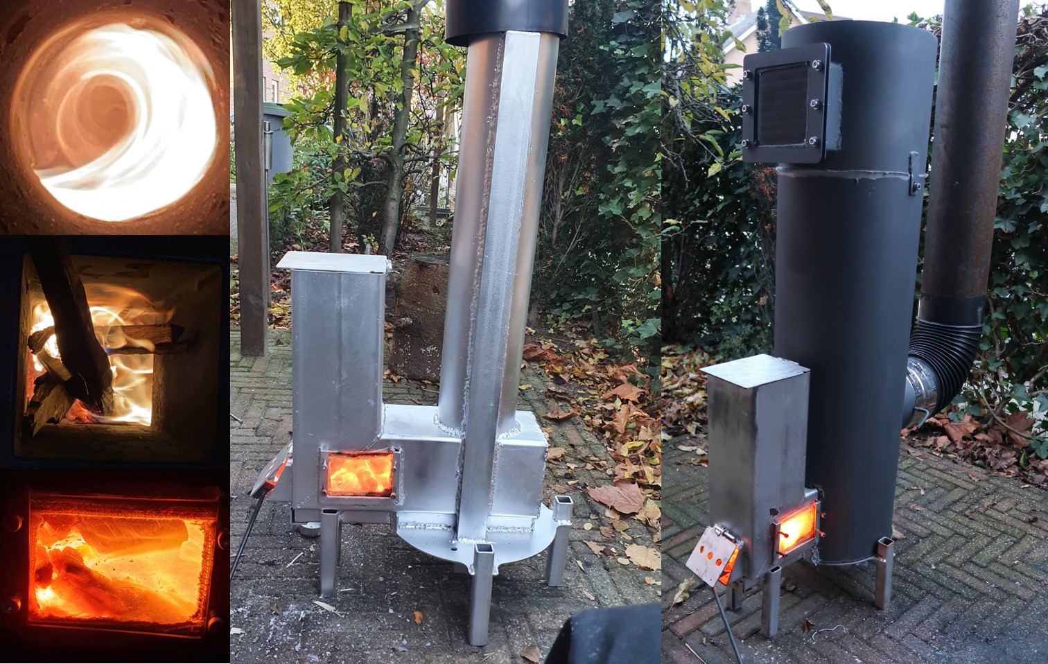 Section view / part naming: 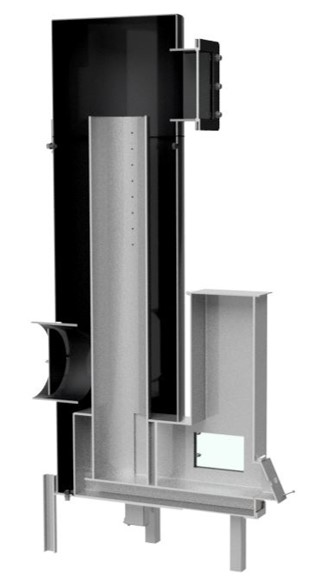 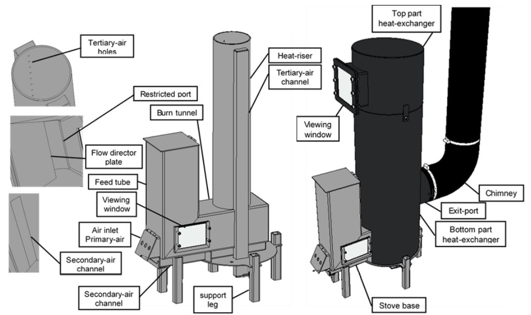 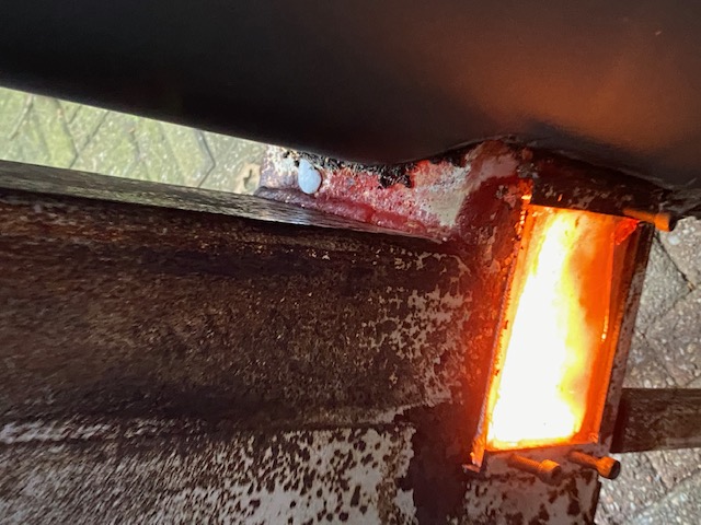 New design New designWhile i was writing the design rapport for the Vortex Heater i encountered your Vortex Stove design on this forum. I was fascinated by how the whole flame pattern was visible with an efficient stove design. So the idea for a new stove design was born. The idea was to replace the stove base with your vortex design and keep the heat exchanger more or less the way it is. Als in this design manufacturability is key, it was intended to lasercut + bend (at a local metal working company) every part snap is together an weld it. The new stove base was designed as a skeleton for dry stacking fire insulating brick / vermiculite. In the plates are holes as said that was for the idea of screwing the vermiculite but if not used they can be welded shut. Skeleton for insulating material: 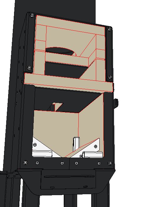 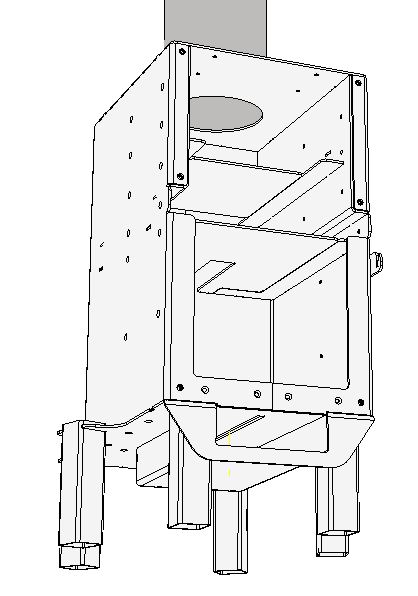 The problem is that i almost wanted to produce it, but with sky high stainless steel prices these days the price for only the sheetmetal was 500 euro's without being sure or this design will work properly. So it is just a little design verification to share this design. (This design is based on an 4 inch system presented on this tread.) Maybe these questions could be answered, 1. Will this work with fire resistant bricks instead of vermiculite (or other material that can be dry stacked)? 2. What is meaned by putting the top exit further away in your prototypes it looks the same? 3. is the secondary air properly done? I may understand the process not quite well enoung but i am try to make a properly working stove.  Thanks in advance |
|
|
|
Post by Vortex on Sept 21, 2021 13:20:49 GMT -8
1: The firebox should be firebrick, preferably about 50mm thick on the 6" / 35mm thick on the 4". Vermiculite board is good for the afterburner (but not if it's going to be used damp). The afterburner needs to be made of highly insulating material, whereas the firebox ideally needs some mass.
2: In my 4" prototypes the exit is at the rear, not on top of the top chamber, as yours is. That may have a negative effect, I haven't tried it so cant say for sure.
3: Where is the secondary air, I cannot see it?
The 4" seems to need more primary and secondary air proportionally than the 6". Easiest way to do the secondary air is to have a small gap between the door and frame, all the way around, 3mm / 1/8".
A few other things: The V-shaped floor is better slightly lower down than in your drawings (20mm lower on the 6" / 13mm on the 4"), and it benefits from a 'threshold' which the top of is half the height of the primary air hole.
|
|
|
|
Post by Karl L on Sept 21, 2021 22:26:36 GMT -8
Hi Trev, can you say more about why you need firebrick (thermal mass) in the firebox?
What happens if you use, say, vermiculte board for the firebox?
|
|
|
|
Post by Vortex on Sept 22, 2021 0:42:40 GMT -8
|
|
Forsythe
Full Member
   Instauratur Ruinae
Posts: 208
|
Post by Forsythe on Sept 22, 2021 0:59:55 GMT -8
…can you say more about why you need firebrick (thermal mass) in the firebox? What happens if you use, say, vermiculte board for the firebox? Trev’s got a lot more working knowledge than I do — so definitely defer to his advice here — but I’m 95% sure the dense refractory (firebrick or castable) serves 2 functions: 1) Dense refractory material has more mechanical strength, and thus will stand up to the abrasion of repeated wood loading far better than insulating refractories like vermiculite board (although some folks report decent success using a hardening additive [sodium silicate “waterglass”] in insulated refractory like ceramic fiber board — but I would hasten to say that water and vermiculite usually don’t play well together, and the 60% water to 40% sodium silicate used in most waterglass would probably compromise the vermiculite board more than it would rigidize it.) 2) Dense refractory materials will hold heat after the peak of the burn, and [in theory] help to more cleanly finish-off the coaling phase at the end of the burn cycle…instead of slowly smoldering into a long, slow, dirty, charcoal phase. (The dense material acts as a thermal fly-wheel, giving back heat at the end to continue the clean burn — whereas purely insulative material is a little better at starting the clean-burn early in the burn cycle [because it doesn’t soak up the early fire’s heat.] So…The best results appear to be from a moderate-thickness (1.5-2 inch thick) dense/rigid refractory material in the interior of the firebox, but surrounded by lightweight insulative refractory to concentrate heat in that firebox and afterburner. (The afterburner is best made with insulative material to keep the secondary burn in full-tilt, using heat lent from the primary burn in the firebox.) Edit: whoops. I guess Trev posted while I was clacking away, before I hit send. Didn’t know he had already responded. |
|
|
|
Post by martyn on Sept 22, 2021 2:05:40 GMT -8
I cant find the exact make up of vermiculite board as it seems to be a secrete ?
However I think it contains about 10% powdered clay 10% hydrated cellulosic gel (whatever that is) and 5% waterglass.
I guess waterglass is a binding agent?
The subject has been discussed on several forums I frequent but I have never seen a conclusive fact sheet.
Anyway from my own personal experience vermiculite eagerly sucks in waterglass and a couple of coats, wet on wet, will toughen the surface and add some protection but wont improve the structural integrity.
Once the board is treated with waterglass and the surface is dry, it wont allow any more to soak in as the surface is now sealed. If you do add more it simply flakes off !
It is the same with ceramic fibre board, you can paint on a couple of coats but try to add any more and it cracks and flakes off.
|
|
|
|
Post by sanderg on Sept 27, 2021 11:39:20 GMT -8
1: The firebox should be firebrick, preferably about 50mm thick on the 6" / 35mm thick on the 4". Vermiculite board is good for the afterburner (but not if it's going to be used damp). The afterburner needs to be made of highly insulating material, whereas the firebox ideally needs some mass. 2: In my 4" prototypes the exit is at the rear, not on top of the top chamber, as yours is. That may have a negative effect, I haven't tried it so cant say for sure. 3: Where is the secondary air, I cannot see it? The 4" seems to need more primary and secondary air proportionally than the 6". Easiest way to do the secondary air is to have a small gap between the door and frame, all the way around, 3mm / 1/8". A few other things: The V-shaped floor is better slightly lower down than in your drawings (20mm lower on the 6" / 13mm on the 4"), and it benefits from a 'threshold' which the top of is half the height of the primary air hole. Thanks for your answer but a couple of remarks/comments on this 1. So something like ceramice fibre board for the afterburner for outside use, or something else? 2. The design of peterberg feautures this in some of his dsr designs so i think it wil work. 3. If you leave a small gap between the door and the frame you can't really call this secondary air i think. You don't really preheat the air. I thought it worked like this with a tube which goes below the slope insulation like the design of martyn with the copper tubes. 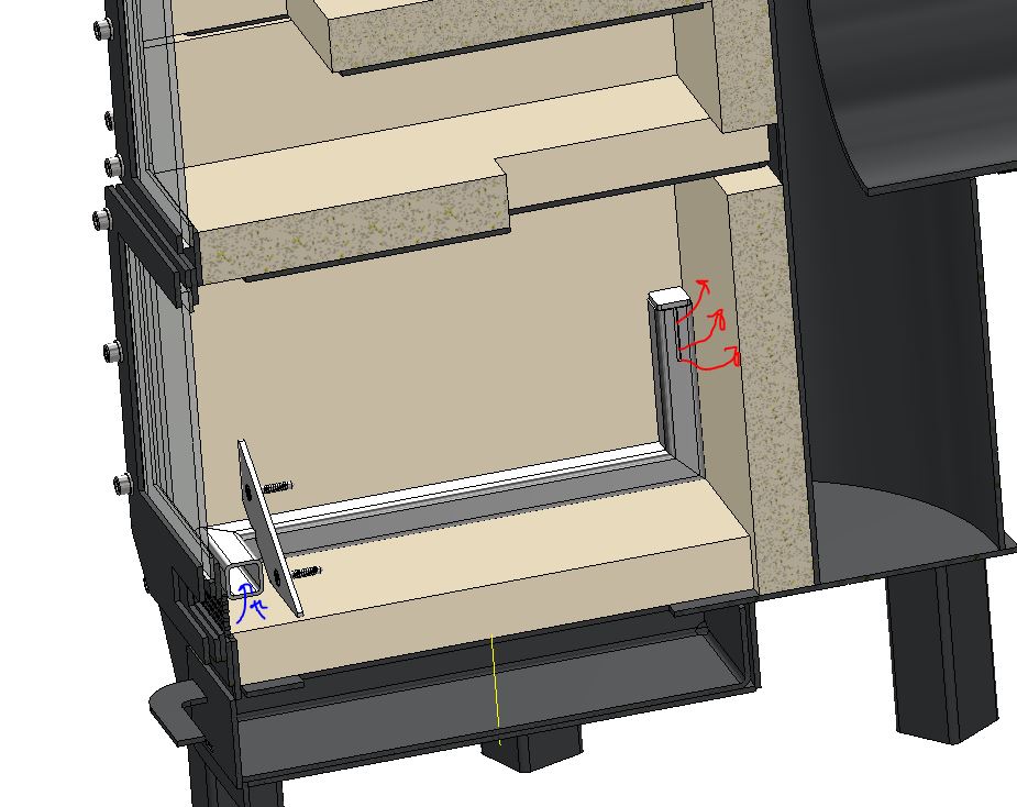 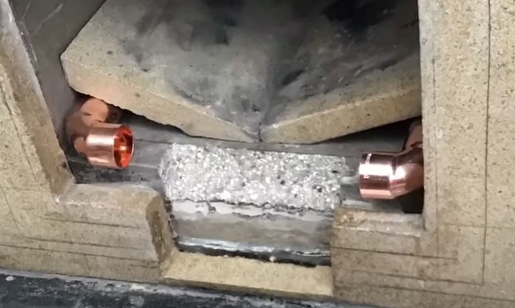 4.Clear! |
|
|
|
Post by martyn on Sept 27, 2021 12:24:51 GMT -8
I tried lots of different things while experimenting with my version of Trevs vortex stove but I never achieved the success or consistently that Trevor has … so I would recommend following his dimensions and material list as close as possible!
My version worked fantastically well one day and them it would play up the next, that could be put down to a number of things as I did follow the dimensions but deviated away from using the exact same firebox materials.
There could of been many other factors like fuel or chimney or back pressure resistance etc …
So in my opinion you should keep as close as possible to Trevors design.
|
|
|
|
Post by Vortex on Sept 27, 2021 13:26:51 GMT -8
1: The firebox should be firebrick, preferably about 50mm thick on the 6" / 35mm thick on the 4". Vermiculite board is good for the afterburner (but not if it's going to be used damp). The afterburner needs to be made of highly insulating material, whereas the firebox ideally needs some mass. 2: In my 4" prototypes the exit is at the rear, not on top of the top chamber, as yours is. That may have a negative effect, I haven't tried it so cant say for sure. 3: Where is the secondary air, I cannot see it? The 4" seems to need more primary and secondary air proportionally than the 6". Easiest way to do the secondary air is to have a small gap between the door and frame, all the way around, 3mm / 1/8". A few other things: The V-shaped floor is better slightly lower down than in your drawings (20mm lower on the 6" / 13mm on the 4"), and it benefits from a 'threshold' which the top of is half the height of the primary air hole. Thanks for your answer but a couple of remarks/comments on this 1. So something like ceramice fibre board for the afterburner for outside use, or something else? 2. The design of peterberg feautures this in some of his dsr designs so i think it wil work. 3. If you leave a small gap between the door and the frame you can't really call this secondary air i think. You don't really preheat the air. I thought it worked like this with a tube which goes below the slope insulation like the design of martyn with the copper tubes. 1. I've never used Ceramic fibre board damp so cant say if it would be OK, but I've never heard of it being sensitive to it either. I would expect most refractories to have a shorter life expectancy if used damp as the moisture in the material expands when heated and damages it. 2. You cannot compare 2 different types of stoves and presume that what works in one will work in the other. The resistance / back pressure that the top chamber creates in the Vortex stove seems to be a critical aspect necessary for it's correct functioning. Shortening that chamber will almost certainly reduce the resistance, that would have a negative effect on the vortex and secondary combustion. You might be able to make up for it in some way by increasing the surface area of the top chamber, but then again you might not. 3. Secondary air doesn't necessarily have to be heated. Most metalbox stoves have secondary air, but most are not preheated. I've tried all sorts of preheated secondary air systems on the Vortex stove, none of them seemed to be of any benefit. |
|
|
|
Post by Vortex on Sept 30, 2021 10:59:42 GMT -8
Forum member lums kindly sent me this video of his test model Vortex stove: |
|
|
|
Post by Vortex on Oct 1, 2021 6:44:00 GMT -8
I sent my testo off for repair and re-calibration 5 weeks ago, finally got the quote back today: €958.25  One member has kindly sent me a donation towards it, but it still leaves a lot to pay, so if anyone else can help out it would be very much appreciated. Thanks.  |
|
Forsythe
Full Member
   Instauratur Ruinae
Posts: 208
|
Post by Forsythe on Oct 1, 2021 19:26:45 GMT -8
3. If you leave a small gap between the door and the frame you can't really call this secondary air i think. You don't really preheat the air. I thought it worked like this with a tube which goes below the slope insulation like the design of martyn with the copper tubes. 3. Secondary air doesn't necessarily have to be heated. Most metalbox stoves have secondary air, but most are not preheated. I've tried all sorts of preheated secondary air systems on the Vortex stove, none of them seemed to be of any benefit. Quoting Trev here but intending mostly to respond to Sandberg’s comment: I really do think the airframe / door gap produces what can be legitimately called “secondary air” — and I think the dense refractory plays an important role in this. (Meaning: I doubt ceramic fiber board or vermiculite in the interior surface of the firebox would produce quite the same effect.) Because the stream of this “secondary air” is introduced as a thin sheet of air directly along the walls of the firebox, it will behave as most thin streams do, and, unlike a turbulent *column* of air, will “laminate” to the firebox walls as it streams rearward toward the back of the firebox, where it then is drawn upward with —and gently mixed with— the pyrolized woodgas as it exits the top of the port into the afterburner. From what I can tell, *Laminar flow* vs *turbulent flow* play critical roles in the vortex design. Inside the firebox, laminar flow allows the incoming secondary air to absorb heat from the dense firebox walls (which it wouldn’t do quite as well with insulative refractory) —and since the sheet of air remains laminated to those walls, it doesn’t burn up completely until mixing at the top port. [Trev had mentioned previously that secondary air pouring in through a “column” as in the pipe/tube or “cobra” design seemed to always disrupt the formation of the double ram’s horns in the afterburner. So it would appear that laminar flow here is as critical to the even-mixing of the secondary air as it is to the preheating.] Turbulent flow, however, is then utilized right where the design needs it: *in and above the afterburner.* By flipping those vermiculite boards to the rippled-side facing inward, this creates swirling eddies of gas along the afterburner walls, thoroughly mixing and completely burning the woodgas — via “turbulent flow”. (The turbulence ensures that no “sheets” of unburned woodgas stream through the afterburner, and that the “sheets” of secondary air no longer remain laminated to the stove walls. The turbulence also would have the beneficial effect of additional flue-gas resistance — slowing the flow by redirecting stream inertia into tiny, swirling [*heh*] vortexes 😉) Here’s a YouTube explainer vid about those two critical patterns of fluid dynamics: youtu.be/9A-uUG0WR0w I sent my testo off for repair and re-calibration 5 weeks ago, finally got the quote back today: €958.25  One member has kindly sent me a donation towards it, but it still leaves a lot to pay, so if anyone else can help out it would be very much appreciated. Thanks.  That really sucks about the Testo repair costs, Trev. If I had the means, I’d gladly donate, as your contributions via this thread have been such a huge help to me. Unfortunately, I’m on a shoestring budget, myself. …was it the thermocouple that went bad? I read that high-heat thermocouples and their wires have to be made of rare earth metals like platinum in order to give accurate readings above 1500°… I guess that would explain why the units are so shockingly expensive to purchase and/or service… I do hope others can help you out with that much-needed equipment repair. |
|
|
|
Post by Vortex on Oct 2, 2021 9:10:22 GMT -8
The secondary air between the door and frame is on all 4 sides so some would also stream across the top. The bottom is below the threshold so would be directed up the inside of the door. The air frames I've seen on this forum have all had their slits facing across the firebox not down the side walls.
My 6" stove has smooth sides in the afterburner, but both the 4" versions I've built have wrinkly side vermiculite facing inwards. I've wanted to try it with all wrinkly surfaces on the 6", but so far have only done it with the roof, as at the moment the sides are Insulating Fire Brick and the afterburner floor/firebox roof is dense cast, so it would mean re-organising the whole top of the stove. It's high up on my to-try-out list though.
The top chamber is all wrinkly side vermiculite, but that's to create more resistance to flow without restricting the CSA, which helps keep the vortex nicely in the afterburner. The top chamber shouldn't need to be insulated, I'm only using vermiculite board there as it's the easiest thing for experimenting with. It may actually be better if it wasn't insulated, as it would suck more heat out of the gasses making them denser and slower - more for the to-try-out list.
The testo needed all the sensors replacing, a new pump, the connector to the probe (which is what caused the thermocouple to keep dropping out), a couple of O-rings and recalibrating.
I'd like to thank the people who have helped out with it, I very much appreciate it, thank you!
|
|
Forsythe
Full Member
   Instauratur Ruinae
Posts: 208
|
Post by Forsythe on Oct 2, 2021 9:42:51 GMT -8
My 6" stove has smooth sides in the afterburner, but both the 4" versions I've built have wrinkly side vermiculite facing inwards. I've wanted to try it with all wrinkly surfaces on the 6", but so far have only done it with the roof, as at the moment the sides are Insulating Fire Brick and the afterburner floor/firebox roof is dense cast, so it would mean re-organising the whole top of the stove. It's high up on my to-try-out list though. The top chamber is all wrinkly side vermiculite, but that's to create more resistance to flow without restricting the CSA, which helps keep the vortex nicely in the afterburner. Right! Sorry. I’ve been laser-focused on that 4” cooktop model (which dumps heat into the top plate without the top chamber,) and designing with the velocity-slowing and gas-mixing effect afforded by the corrugated surfaces for the 6” version I have in the works. (That latest summer 2021 cooktop 4” test version you made has SO much potential for a host of different use-cases I’m after. 👍) |
|
|
|
Post by peterberg on Oct 5, 2021 23:37:17 GMT -8
The testo needed all the sensors replacing, a new pump, the connector to the probe (which is what caused the thermocouple to keep dropping out), a couple of O-rings and recalibrating. Trevor, I hate to say this, but it's highly unlikely the sensors just broke down the day before you sent the Testo to the calibrators. And all at the same time, even less likely. I've had a similar problem some years ago, although not as severe. I tend to doggedly follow the calibration intervals, nevertheless I sent the device in once and the CO cell appeared to be broken accompanied by the O² cell way out of line. This resulted in all the tests performed during a couple of months before that were worthless. The soon as I payed the (hefty) bill and used it again the results were mediocre at best. While those same configurations had been performing excellent before! Also, given the fact that you've stretched the calibration intervals by multiple months at least, most or even all tests of the past year or so could be invalid. Sorry. |
|


