|
|
Post by Vortex on Dec 14, 2021 12:53:32 GMT -8
patamos very kindly sent me THIS VIDEO of the finished Vortex stove he's built for Brent in Canada, and the description below:  The various iterations with the steep V-sided floor never quite worked out. Even once I thinned its mass to 2" and added big air slots front and back it kept bogging down to incomplete burns. Glass was sooting up and big chunks of unburnt wood were leftover. Not happy... Tweaks to downstream aspects of the system were helping - particularly extending the tongue in the backrest-bell to make it more of an upper-lower flue run... Super glad I put that in, and big thanks to everyone who chimed in response to my questions about what to do there. But things were still way off, and my sense was that too much air was bypassing the fuel up the side walls. Unburnt O2 running past (rather than into) the flame is just a bunch of cooling ballast gas clogging up the system... Next tweak was to close off the side wall air ports which improved the coaling phase, but still things were sluggish. So we then reopened some side air at the front and back. Again, minor improvement, but still soot covered the glass from mid burn onward. With each tweak it grew clear that the V was not going to work out because we had no way of concentrating the air flow where we wanted it to go when we wanted it to. We could prevent early stage bottom air supply by placing a chunk of 2x2 in there. I thought I was a pretty smart fella for coming up with that idea. But evidently I was more of a fart smella... Residency time in the fire chamber was not too slow, but temperature was too low and turbulence was still way off. The door had about 2" of CSA but this had little effect and I wasn't interested in modifying a store-bought cast iron unit. So I rigged up a metal floor with air slots front and back and along the sides. And we loaded up a bunch of not so dry wood... and voila. She started hummin. That video is about 20 minutes in and the mild soot on the glass from early burn was still cleaning up. This variation of metal floor 'bottom air' supply is spread out mostly over 3" across the back and 3" across the front (with numerous 1/2" holes), and along the bottom corner side-walls via 1/2" x 12" spaces. There are no air holes in the middle area of the floor so as to encourage the fuel to burn from the ends and perimeter towards the middle. Otherwise that mid-region of fuel (which is directly under the ceiling exit port) will burn first, creating a(nother) situation in which the air supply would be blowing past the fuel... All in all, i think this kind of air-port layout may be as good as we can get with a non-adjustable air supply system. Once things get to coaling phase one can rake the coals forward and/or back onto the ports to turbo blast them. We may play around with the floor-air configurations a bit. This is just a thin piece of 16 gauge mild steel I had kicking around. Once I think we have nailed it I will make something out of 1/4" btw - the 2mm piece of mild steel I have in the floor of my tauran triple shoe box is still holding up after 4+ years. Must be the cooling effect of under-air flow. Now that we are getting closer to ideal temperature and pull, we might tune down the ceiling port which I hogged out to 6" x 2.25" (knowing it would be way easier to shrink that down than get in there and carve out again...). In the video we had shrunk the length by 1", but we might cut up some old 3/4" thick kiln shelf to narrow the sides and raise the floor closer to Trev's specs of a 5" system size. I think first though Brent is going to place a divider across the midsection to see what happens with a sideways tauran double port. Should be fun to watch  One last thought for now: I think Trev is right about the downstream harvesting dynamics having negligible impact on combustion dynamics, particularly when the fire is really cranking. When our combustion process was staggering the bypass port in the backrest was very influential. But once combustion was in the happy zone the bypass adjustments had very minor and gradual effect
|
|
|
|
Post by hof on Dec 15, 2021 2:05:40 GMT -8
I'd go a little higher with the secondary air. Where will the air inlet and control for the secondary be? 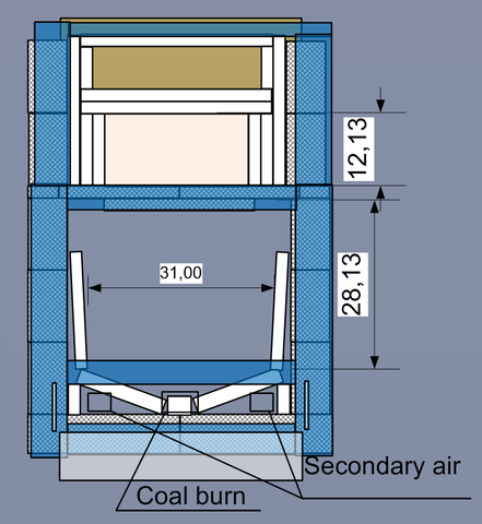 Planned Berg`s door with through door`s frame air feed. I still thinking about how to unite to secondary air feed doors. Also there would be coal burning door. Looks a bit complicate, but sometimes it needs to have separate control. |
|
|
|
Post by Vortex on Dec 15, 2021 5:50:41 GMT -8
An ash-box underneath makes it a lot easier to do the coal burn air. Can you not bring it up from below?
Do you mean air frame for the secondary air? If you use an air frame don't forget to oversize it to compensate for the ISA drag and corners.
If it's any help you don't need the secondary and coal burn at the same time so maybe you could use the same source for them both.
Also don't forget the threshold, without it the primary air will overdrive the fire.
|
|
|
|
Post by hof on Dec 15, 2021 6:30:22 GMT -8
For 160 mm "riser" it need 30% CSA = 60-61 sm2 of air. Through 40x60x2 mm tubes of air frame it could be passed 5.6*3.6*2=40.3 sm2 for both. 20 sm2 could be added with secondary air ports(s).
|
|
|
|
Post by Vortex on Dec 15, 2021 7:22:55 GMT -8
Your chimney size is 160 mm?
160 mm system size = CSA 20109 mm2 x 30% = 6033 mm2.
40mm x 60mm = 2400 mm2.
56mm x 36mm x 2 = 4032 mm2
Total 6432 mm2.
I would highly recommend you keep the primary air adjustable upto 30%, and add the 10% secondary and 3% coal burn air from a separate source.
|
|
|
|
Post by patamos on Dec 15, 2021 10:17:17 GMT -8
I'll second that. Very hard to tune otherwise. Also, with coal-burn-air from the ash box you will get fairly even distribution; but with a small port at the front the faster air flow will likely burn the coals near the front first and thereafter bypass through that gap into the open space. When the fire is roaring secondary air will mingle well enough near the ceiling port. But with coals, you want to aim the air right at them.
|
|
|
|
Post by Jura on Dec 16, 2021 11:00:17 GMT -8
patamos This variation of metal floor 'bottom air' supply is spread out mostly over 3" across the back and 3" across the front (with numerous 1/2" holes), and along the bottom corner side-walls via 1/2" x 12" spaces. There are no air holes in the middle area of the floor so as to encourage the fuel to burn from the ends and perimeter towards the middle. Thank you so much for your follow up. I'm familiar with Alex chernov's 2 grate firebox. I watched your video..And I'm not sure if I get your words describing air distribution - propperly. is this image -that my mind draws from your descrition - correct ? [img src="  " alt=" "] |
|
|
|
Post by patamos on Dec 16, 2021 19:50:41 GMT -8
Ya more or less air along the sides can be just a metal sheet that is 1" narrower than the ashbox roof opening ; with splits as struts on both sides in the front and back of the ash box that can hold the deck up. Maybe do that part in clay-sand mortar so you can adjust if necessary... Also, I have about twice as many holes each end. kinda 4 staggered rows worth with 1/2" to 3/4" spacing between them. This is just what came to mind in getting a long narrow firebox to work well enough. Could be there is some variation in ratios that might work better... have fun |
|
|
|
Post by lordsimon on Dec 17, 2021 3:51:49 GMT -8
I tried both of them. But noting works for me. Is it possible to get the file sent to me? Regards Simon |
|
|
|
Post by Vortex on Dec 17, 2021 5:13:34 GMT -8
Hi Simon, Send me a private message through the forum with your email address and I'll send it to you.
|
|
|
|
Post by Vortex on Dec 17, 2021 12:54:23 GMT -8
WOW! 1000th post on the thread As I mentioned earlier, I've been playing around with different afterburner secondary air setups again. In a recent storm my chimney cowl got ripped off and I've borrowed a friends fancy anti-down draft cowl made by Windkat, it has an exit CSA of 2.5 which has increased the gas flow through my system making it overfuel briefly at the same point every burn. Instead of just increasing the top chamber resistance to offset the increased gas flow, I've been using the opportunity to experiment with different secondary air systems to see how effective or not they are at preventing overfueling. The main problem I found before with secondary air in the afterburner was if I could get enough air in it messed up the vortex. I guess even 450c air in 900c gas is relatively dense and heavy and reluctant to mix. Having secondary air means adding another air control though, as if it's just fixed full open, then 90% of the time you don't need it and it's just raising the O2 content of the gas flow and moving heat out of the mass through the chimney. For these experiments I've been using a large magnet that I can slide over a hole in the side of the stove to open and close it. My first trial this time was to try just 1 sidewall covered in 6mm holes, it was a good idea to do one side as I could see the difference quite clearly, when the side without the secondary air was overfueling the side with wasn't. The holes in the side wall only worked on the lower half though as the vortex was pushing into the top ones, so on the next trial I just had 3 rows of six 6mm holes on the lower part. This worked well as the air was working with the vortex and speeding it up, and made an audible roar. Next I tried the same on both sides and as the air source was divided between the 2 sides the effect was less dramatic. After that I added forty 6mm holes evenly spread out over the back wall, this combination was mine and the testo's favorite, lots of small holes mixes the air into the gases well without disturbing the vortex. I went on to try out larger holes in the sides, sides and rear, slits down the bottom sides and then just two 12mm holes in the rear wall in the centers of the vortices. This seemed to push the vortex forward a bit and made it into 2 amorphous blobs, whereas the small holes made lots of different colored streaks within the vortex. The most striking thing though was the difference in the color of the vortex, with the secondary air it's noticeably brighter, like the color of the sun.     There is a short VIDEO HERE of the best version. |
|
Forsythe
Full Member
 Instauratur Ruinae
Posts: 208
|
Post by Forsythe on Dec 17, 2021 15:40:55 GMT -8
patamos very kindly sent me this… The various iterations with the steep V-sided floor never quite worked out. Even once I thinned its mass to 2" and added big air slots front and back it kept bogging down to incomplete burns. Glass was sooting up and big chunks of unburnt wood were leftover. Not happy... Tweaks to downstream aspects of the system were helping - particularly extending the tongue in the backrest-bell to make it more of an upper-lower flue run. […] But things were still way off, and my sense was that too much air was bypassing the fuel up the side walls. Unburnt O2 running past (rather than into) the flame is just a bunch of cooling ballast gas clogging up the system... Next tweak was to close off the side wall air ports which improved the coaling phase, but still things were sluggish. So we then reopened some side air at the front and back. Again, minor improvement, but still soot covered the glass from mid burn onward. With each tweak it grew clear that the V was not going to work out because we had no way of concentrating the air flow where we wanted it to go when we wanted it to. We could prevent early stage bottom air supply by placing a chunk of 2x2 in there. […] Residency time in the fire chamber was not too slow, but temperature was too low and turbulence was still way off. The door had about 2" of CSA but this had little effect and I wasn't interested in modifying a store-bought cast iron unit. So I rigged up a metal floor with air slots front and back and along the sides. And we loaded up a bunch of not so dry wood... and voila. She started hummin. That video is about 20 minutes in and the mild soot on the glass from early burn was still cleaning up. This variation of metal floor 'bottom air' supply is spread out mostly over 3" across the back and 3" across the front (with numerous 1/2" holes), and along the bottom corner side-walls via 1/2" x 12" spaces. There are no air holes in the middle area of the floor so as to encourage the fuel to burn from the ends and perimeter towards the middle. Otherwise that mid-region of fuel (which is directly under the ceiling exit port) will burn first, creating a(nother) situation in which the air supply would be blowing past the fuel... All in all, i think this kind of air-port layout may be as good as we can get with a non-adjustable air supply system. Once things get to coaling phase one can rake the coals forward and/or back onto the ports to turbo blast them. […]We may play around with the floor-air configurations a bit. Now that we are getting closer to ideal temperature and pull, we might tune down the ceiling port which I hogged out to 6" x 2.25" (knowing it would be way easier to shrink that down than get in there and carve out again...). In the video we had shrunk the length by 1", but we might cut up some old 3/4" thick kiln shelf to narrow the sides and raise the floor closer to Trev's specs of a 5" system size. [emphasis added —Forsythe] One last thought for now: I think Trev is right about the downstream harvesting dynamics having negligible impact on combustion dynamics, particularly when the fire is really cranking. When our combustion process was staggering the bypass port in the backrest was very influential. But once combustion was in the happy zone the bypass adjustments had very minor and gradual effect I could be wrong, but I bet the change to the firebox port’s aspect ratio is what caused the sooty problems with cooling air coming in too fast and racing through that hogged-out port. …This immediately jumped out at me ‘cause I’ve been reading a lot about waste oil burner nozzle designs the past week, learning just how important nozzle (read: port) shape is in changing A) fluid pressure and B) mixed fuel/air ratio —both *behind and in front of* that constriction to input flow. (Backstory: I need to hold cone 14/15 for a couple hours in the kiln to evolve accilar mullite in AL+MgO+Mn doped kaolinic refractory tiles, which isn’t easy with woodfiring 😅 … but it can be done easily with (viscous) waste vegetable oil — so long as the oil is atomized in order to mix properly with combustion air.)  It amazes me how the TINIEST little tweaks to aspect ratio of the fuel nozzle’s ventury contraction and/or spray orifice — which is very much analogous to the firebox’s top port shape, and the concentrator disk in natural-draft TLUDs — have hugely consequential impact on head pressure, fluid speed, rate of mixing, and even combustion location— on both sides of that port …all due to Bernoulli’s principle and the Venturi effect..
That change in fluid speed relative to pressure (caused by constriction in the input path) is what causes the flame to burn clean, completely, and hot … or… sooty, partially, and over-cooled. [image comparing the homologous, functional similarities between 1) fuel oil atomizing nozzles' orifice constrictions, 2) TLUD gasifier concentrator disks, and 3) rocket stove port aspect ratios 👇]  At least... I'd wager on it. Best guess. I'm curious now if opening up the firebox size [making up for the reduced head pressure caused by the fatter port ...by nixing the sloped floors to accommodate all that extra sucked-in room air...] is working because its creating extra pressure from the additional volume of pyrolyzed woodgas, instead. ...Like... I wonder what would/will happen if the port is changed back to spec now that the firebox is approx 30% over-spec in its own volumetric space, too. 🤔 |
|
|
|
Post by patamos on Dec 17, 2021 22:56:58 GMT -8
Ya, all that for sure this taller throat, now pushing 3+ inches thick, also seems to make that flame want to jet straight up and crash pretty hard into the ceiling. So the palm tree effect is being exaggerated. And I recon y'all ought to know that at any time i catch even a glimpse of complex geo-physical equations my eyes instantly glaze over... But when i think of it in terms of fluvial geo-morphology everything makes gut sense to me. Interestingly enough, I recently replaced the stumbler in the middle of my (own heater's) port with a wider piece of kiln shelf. This has made for by far the biggest restriction yes, bring the dimensions of my exit down to a pair of 4.5" x 1.5" . And lo and behold, the pull was instantly 20-30% stronger. So ya, it all makes sense one way and another... Anyway, I just today narrowed the port on Brent's firebox to 6.5" x 1.75" and something just wasn't right no matter how much i tinkered. Then... I happened to open the front door (of the very air tight building)... and THAT was the answer. not the first time its happened either... |
|
|
|
Post by martyn on Dec 18, 2021 13:24:10 GMT -8
Trev, you mention about suppling 3% air below the coals, what would happen if you offer a lot more air during the coaling stage?
|
|
|
|
Post by Vortex on Dec 18, 2021 15:57:10 GMT -8
It seems to work best when the air is just slowly percolating up through the coals. Increasing the volume just tends to blast holes through them, which the air then takes as the path of least resistance, the increased turbulence blows the flames out and cools the coals.
|
|


