|
|
Post by peterberg on Oct 12, 2008 11:35:07 GMT -8
That last proposal did look like the classic potbelly stove at first. But, maybe there is still an idea in there... The reason why rocket stoves work like they do is, in my opinion, the incoming air is pushing the flames in an unnatural direction. Flames want to go up, and via the shortest route with that. This effect is causing a lot of turbulence with excellent mixing of air and unburned gases. Coupling this with an insulated burn chamber and heat riser will result in very efficiently combustion. I've made three line drawings which shows the pushing-away properties of the air. The first is the classic J-shape, the second the setup which I am currently working on, and the third is one with the heat riser on top, like Tom has written about. 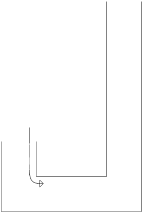 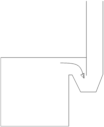 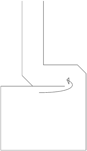 So, Tom, probably it can be done provided enough air is reaching the bend. Air intake from below only won't work, I'm afraid. Everything else, like insulated heat riser and burn tunnel still applies. |
|
|
|
Post by chronictom on Oct 12, 2008 12:30:49 GMT -8
I have actually been considering something very similar to the third on using the old cast stove we have right now.
It is just a small box stove, with the pipe coming off the rear and heading up into the chimney, actually works surprisingly well for warming the house for now, but as it gets colder it won't.
I was considering putting a 90 where it comes out and a 2 foot piece with 2 90's and another 2 foot piece with another 90 heading back up the original path then covering the whole thing in cob.
I've been hesitating though, because I'm not sure if it may not be better to shorten the upper horizontal run, and put a riser in with barrel with the outlet off the bottom into the chimney....
lol, so many options, so little time...
|
|
|
|
Post by peterberg on Oct 29, 2008 12:54:28 GMT -8
Here I am again. Double bell has been built, of course I've changed it several times. The design has been fixed for the moment, nearly all of my spare time is going into gathering and processing firewood. So development is on hold until approximately Christmas. The second bell is half the size of the first, upstream channel from the bottom of the first to the bottom of the second bell is by a brick chimney at the back. To encourage initial draft a permanent leak of about 2 square inch has been provided between first and second bell and between second bell and the chimney exhaust. Just to be on the safe side I've made a bypass valve of full system size from first bell straight into the chimney. During three runs in order to completely drying the whole thing the bypass valve was very handy, after that period the intentional leaks were sufficient to make a cold start very easy with no problems whatsoever. Testing results from this setup are very nice. see pberg0.home.xs4all.nl//pictures/large/test081027.gifThis test run is started with 8 pounds soft wood, lit on top. And a refill with another 8 pounds at 44 minutes. Intake settings where fixed for the entire run. As visible in this graphic the O2 and CO levels are coming down together at the height of the burn when the efficiency is at its peak. This is very peculiar behavior, the mass heaters which I am aware of produce a CO level which is coming up at the height of the burn to rise to a very high sharp peak. Mark the exhaust level, the purple line, which is very low and follows a slow but steady incline. And a flat line when the fire is going into glowing phase. Temp is in Celsius, in Fahrenheit the start is at 77 F, and top level after 90 minutes is at 230 F, enough to avoid condensation in the second bell. Efficiency is at its peak 97.6%. About the construction: admittedly, this one is clearly a bit on the complicated side. In the drawings, the animated gif pberg0.home.xs4all.nl//pictures/proto4.gif is showing the copper pipes without a bended piece at the top. The bends have to be there, but were too difficult to draw. Top of the fire box and the first bell are made of refractory castable, top plate could be ordinary concrete pavement slab without rebar in it. Next goal will be the construction of a low mass insulated rocket afterburner. Sizing up to 1.5 times current size is another item on the list. And last but not least: some more pictures. 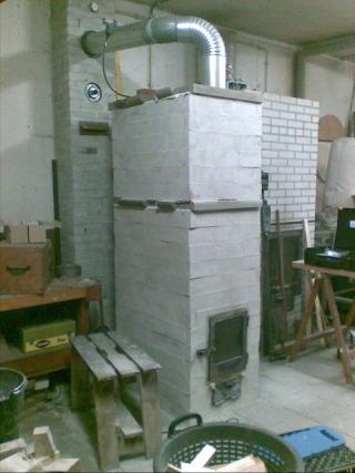 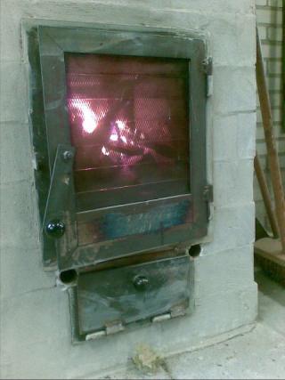 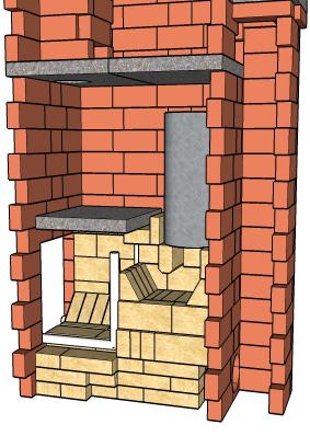 |
|
|
|
Post by rocket_richard on Oct 29, 2008 14:31:03 GMT -8
Wow Peter,
Looks great. Nice sketch-up drawing.
Does the secondary air make a big difference? Did you do any calculations to know how much air to add?
|
|
|
|
Post by peterberg on Oct 30, 2008 9:20:47 GMT -8
Yes, Richard, in fact I did.
70 cm2 added by the loading door, 10 cm2 by the ash-pit and 17 cm2 by the two pipes.
In square inches: 10.85 loading door, 1.5 ash-pit, 2.6 pipes.
The system size is 6", so that will make 28.27 square inches.
The above total openings are nearly 53% of system size.
The pipes could be a little bit larger and the loading door opening the same amount smaller, I do think.
The secondary air through the pipes is absolutely necessary, otherwise the top of the burn will be very dirty. Even so, it is not possible to reach the same effect by opening up the loading door twice as much.
|
|
|
|
Post by chronictom on Nov 2, 2008 15:41:07 GMT -8
is there some way you could add a fresh air feed into the bottom of the riser? The stove burns up some of its available oxygen before that point, so an air inlet right there would give it access to as much as it needed?
|
|
|
|
Post by peterberg on Nov 3, 2008 10:11:52 GMT -8
is there some way you could add a fresh air feed into the bottom of the riser? The stove burns up some of its available oxygen before that point, so an air inlet right there would give it access to as much as it needed? The stove as it is now can get all the oxygen it need. See the test-graphic, at the lowest point there's still around 10% oxygen available. Feeding more air at the hottest point would only rise the oxygen level and cool down the fire. Maybe, when I would cancel the secondary air via the pipes and introduce another preheated air feed at the bottom of the riser it would work just as well. In general, higher efficiency like the graphic do show is only obtainable via condensation of the flue gases. That would require an electrically operated fan and a condensation fluid trap. Too complicated to my taste, I won't go down that route. |
|
|
|
Post by chronictom on Nov 3, 2008 20:43:18 GMT -8
I seem to remember something about using a constricted path to form a venturi? (dont quote me on the word). I think it was in a design of a stove made out of a cylinderical tank. Air fed in the front, through the wood and then it tapered to 1/3 of the size and then came back out to full size. The idea was to the effect of causing all the gases to combine and burn at that specific point... I'm not sure if the idea is valid or applicable here, but thought it might bear mentioning...
|
|
|
|
Post by chronictom on Nov 7, 2008 13:40:31 GMT -8
You keep rebuilding this... what are you using for the mortar when you do?
|
|
|
|
Post by peterberg on Nov 8, 2008 0:09:27 GMT -8
You keep rebuilding this... what are you using for the mortar when you do? I'm using earthenware-clay, mixed with sand. Proportions: 1:1. This is giving a very weak bond, so areas with thermal stress will show up immediately. When dismantling I do clean (scrape) the used bricks above a bucket, add water and the next day it is clay again. |
|
|
|
Post by peterberg on Nov 30, 2008 9:36:14 GMT -8
A word of warning for the individual who's going to build the rocket bell themselves: the first upstream channel show severe cracks at the joint with the first bell.
To avoid this situation it would be better to make the bell a bit deeper and/or wider. In this way it would be possible to have the upstream channel inside the bell. A solution like I've been using for the second upstream channel, in the second bell.
After four hours of firing, hairline cracks appearing around the top corners of the first bell. Not above the loading door, where contraflow heaters frequently have problems with.
The loading door doesn't even have a lintel above it, the bricks are only separated from the metal by some ceramic blanket.
|
|
|
|
Post by hobbsao on Jan 1, 2009 12:48:56 GMT -8
please excuse my ignorance as i am trying to learn everything about rocket heating systems. I was wondering where is the fire burnt in the above drawing? in the bottom hole or the top angled hole?
|
|
|
|
Post by hobbsao on Jan 1, 2009 12:50:28 GMT -8
i am sorry, I meant in the very first drawing at the begining of this post.
|
|
|
|
Post by peterberg on Jan 2, 2009 5:30:11 GMT -8
I was wondering where is the fire burnt in the above drawing? in the bottom hole or the top angled hole? If I understand this question correctly, at all three drawings the fire is burning at the bottom. The first drawing shows the "J" shape of the Evans mass heater with fire at bottom left, the second one do exist as an experiment, the third is only a proposal. A new idea which I am pondering about has to wait to be build for another two months. It is a variant of the third one. |
|
Teach
Junior Member
 
Posts: 89
|
Post by Teach on Jan 15, 2009 16:25:56 GMT -8
Peter, I love the work you are doing by combining these two systems. But I'd like to step things back a little to the beginning posts within this thread on the single bell as opposed to the double.
I have some concerns; First off how would I do any repair work on the rocket once it is encapsulated in brick and mortar? Like for instance if the combustion chambers bricks were cracked and needed replacing?
The double bell is a bit beyond the simplicity of the single so because I also have limited ceiling height, I am leaning more in the direction of the single bell style.
How if any way would the building of the rocket on the outside of the bell affect its efficiency?
I ask this because I like Ianto's vertical feed system better than the horizontal style as it simplifies feeding a smaller fire and by having the complete rocket outside the bell it would make repairs on the rocket much easier than if fully enclosed within the bell. You could use the barrel or do away with it entirely and simply feed the bell.
In this way as stated above, where would be the best height to introduce the hot flue gasses to the bell? The bottom is best for the exit but what about the input?
Lastly, how would we overcome the stress cracking you incurred when building these permanantly? Or would this be a non issue when using proper fireclay mix for a permanant installation?
Enough questions? grin.........sorry. Thanks
Teach....
|
|