|
|
Post by grootebeer on Apr 28, 2021 11:17:46 GMT -8
Has anyone made a DSRI or II completely form castables - or is that a dumb idea?
|
|
|
|
Post by peterberg on Apr 28, 2021 12:22:10 GMT -8
Has anyone made a DSR! or II completely form castables - or is that a dumb idea No, it's not a dumb idea. In fact, the DSR2's final development model was built from refractory castable slabs. The only part that wasn't like that happened to be the superwool liner in the riser stub. Regarding the DSR1, I didn't got as far as a final model. The design was ditched before that stage as being not a viable combustion core using hard materials and a real chimney stack. |
|
|
|
Post by grootebeer on Apr 28, 2021 12:46:18 GMT -8
Thanks Peter - I am groping around to see if it feasible to make a really lightweight version in the 1kW power range. Probably the wrong thread to be asking this since I am really looking at DRSII - it's a tiny workshop, really well insulated. Thanks anyway for your reply.
|
|
|
|
Post by hallinen on May 1, 2021 13:45:20 GMT -8
What I like about the port opening on top is I can shove wood in and not worry about sticks blocking the port. I’ve been tossing my beat up bricks into a cook stove version that is a work in progress but lots of fun. I was intrigued by Peter’s latest video, the tube inferno was mesmerizing.
|
|
|
|
Post by grootebeer on May 7, 2021 2:46:57 GMT -8
I have read the whole thread up to this point. Clearly Peter has done his usual yeoman's work on experimenting and recording his findings - Peter, I could easily envy your creativity, energy and stamina.
I am at the stage where I want to start a parallel vortex effort of my own, and being a lazy sod, am begging the indulgence of others to ask if anyone has summarized the dimensional and structural status to this point?
I was hoping for some kind of dimensional summary of the overall design and components.
Obviously a CAD model would be ideal, but I could work on doing one from a summary, for review and correction.
If a model is imminent, I will shut up and be patient.
|
|
|
|
Post by peterberg on May 13, 2021 11:11:38 GMT -8
There's no definitive model imminent. Mainly due to the fact that I am searching for the simplest and easiest to obtain parts and materials. I ordered four different contenders, once those are arrived, I will be able to test, evaluate and make a choice.
I'll keep you guys informed but don't hold your breath. More work on the website is in the pipeline, namely a translation in Portugese. It is important for the commercial version to be ready around September/October, for obvious reasons. So final design is quite some months off, sorry.
|
|
|
|
Post by peterberg on Jun 13, 2021 8:34:42 GMT -8
Not so much as progress the past month. One order didn't arrive at all, probably due to faulty adressing but I got my money back. I did put another order on hold because of worrying information regarding ceramic fibers. Several kinds of those ceramic fiber will dissolve into lung moist and as such are able to leave the body like that. This is known as half-life or half-value time, similar to radioactive radiation. Expressed in days, not in hundreds of years. Rockwool used in building construction for example has a half-life of 40 days, Morgan Ceramics Superwool 10 days and special high refractory fibers used for vacuum formed risers 70 days. Still not good for the consumer and worse for the installer of those in heaters. There's one catch with Superwool though: when it has been heated to a temperature above 800 ºC (1470 ºF) it will form crystals (Kristabolite) and those resulting fibers won't dissolve at all. This does sound real bad and given the fact that superwool will shrink dramatically when exposed to temperatures above 1000 ºC (1830 ºF), vacuum formed Superwool is off the table. The higher specced Ceramic fibers, also from Morgan Ceramics, doesn't show these behaviour but the best quality binder will give away much earlier. To this end, there's clay added to the binder in the vacuum process which will bake into ceramic while the normal binder is baking off. This clay addition will lower the insulation value quite a bit, by the way. I also aquired two types of riser tubes used in iron foundries to try out, real thin and insulative but dusty and brittle when exposed to high heat. And besides that, those were a little too small diameter for what I need. Given the fact we don't want any fine dust into our exhaust gases I tried to find an alternative. First thoughts did go to real refractory tubes, not uncommon for use as chimney liner in Germany, Austria and Italy. Hard to come by in small quantities but two German producers were willing to send me samples of their thinnest variants. So I have three kinds of these tubes here now, all reassuring hard kiln baked clay ceramics. Two manufacturers were kind enough to send me samples, Hart Keramik close to the Czech border and Müller from Westerwäld. All these were the correct internal diameter, 140 mm (5.5"). One item of 15 mm (0.591") wall thickness, four items of 10.5 mm (0.413") and two items of two feet long sporting wall thickness of just 8 mm (0.315"). The thinnest one turned out to be very brittle and cracked and splintered while being cut using a hand grinder and diamond cutting wheel. So this was the first to reject as being not really suitable. The thicker one from Hart was split along its length and mounted horizontally in the development core. After fired for approximately two hours, running red hot at the far end and cooled down during the night this one showed two cracks in the top half. Both a little over 5" from the rear end left and right, roughly halfway above the port opening. I used this as an indication where the highest thermal stress would be. One thinner item from the same manufacturer was cut the same way and an extra cut was done at right angles over the top half, 5" from the rear end. 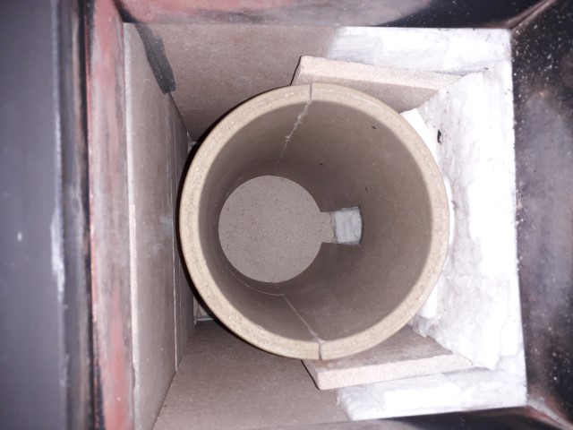 The partition cuts are visable, the superwool bed is there to lift the tube to the right position relative to the ceiling, not to be included in the final design of course. This arrangement survived three hefty burns uptil now so yesterday I decided it was time for a full test. The firebox was loaded with hawthorn again with small planks of pine on top. Under the fuel there are two steel bars arranged in such a way there's some space underneath. This is better for the end of the burn, combustion being more uniform through the depth of the firebox. Combustion air supply through the door frame again, left and right starting 4" from the bottom and up, and a larger slit in the horizontal beam above the door. 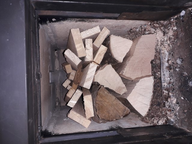 This arrangement yielded good results: good enough for the EU certification tests. 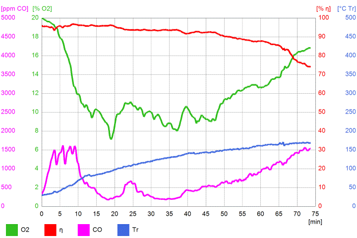 No dramatic jumps in any of the lines, no overfuel situation or super low O² levels. Warming up took a bit longer as compared to an insulating tube but critical point appeared to be between 10 and 20 minutes as before. Checked the afterburner parts this morning, no cracks to be seen despite the ceramic tube has been cherry red at the far end, in and out. Some average numbers: O² 12%, eff. 91.1%, CO 713 ppm, end temp 120.9 ºC (250 ºF). All this is very encouraging, I am happy. Outside temperature is too high now for further testing, I'll do some sketching during the coming week(s). |
|
|
|
Post by Karl L on Jun 17, 2021 10:55:55 GMT -8
There's one catch with Superwool though: when it has been heated to a temperature above 800 ºC (1470 ºF) it will form crystals (Kristabolite) and those resulting fibers won't dissolve at all. Thanks for that, Peter. Where did you see this information about Kristabolite forming from Superwool? |
|
|
|
Post by peterberg on Jun 18, 2021 0:09:45 GMT -8
The information was by mail, not online as far as I know. The firm in Belgium that do the vacuum formed products for foundries was kind enough to come up with this. We had quite extensive email exchange and as a result I didn't order any of their products. In short, providing me with that specific information wasn't in their own interest but they did anyway. Good firm.
|
|
|
|
Post by Karl L on Jun 18, 2021 3:08:44 GMT -8
Thanks for that information. It's good when companies are fully open about their products.
I found an industry response to this concern, with links to some research papers (https://www.ecfia.eu/facts-cs/). It's not easy for me to know how independent the researchers were, but the papers suggest that the bio reactivity of heated High Temperature Insulation Wools is not high.
|
|
|
|
Post by peterberg on Jul 1, 2021 12:39:08 GMT -8
Six more test runs have been done since last time, largely to establish the best position of the ceramic tube in the top box. Yesterday morning I did a complete run and at the end I added two reasonably sized pieces on the glowing coal bed. Just to see what would happen since the EU norm calls for a heater that's at working temperature before the test starts, as opposed to starting with a cold firebox every time. The firebox was filled following the upside down method and lit on top, my normal procedure. The resulting diagram is very interesting, although some explaining is required in order to read it correctly. 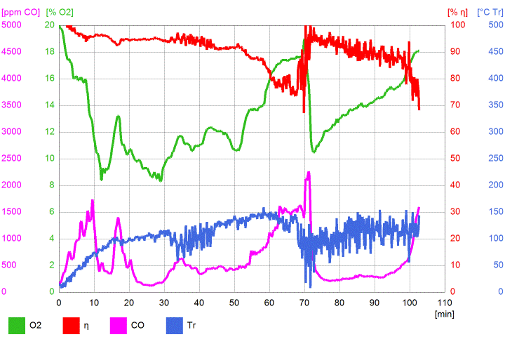 The temperature and efficiency lines are erratic, probably due to a failing thermocouple, so please ignore those. The door was kept open a crack until 17 minutes into the burn, nothing has been done to the heater until the end-of-test at 69 minutes. Uptil that point the run wasn't bad at all, within the EU requirements. After adding the two pieces of fuel the CO line went up a bit and down very steeply and stayed below 500 ppm for about half an hour. I let the whole thing cool down during the day and did another run in late evening, between 8 and 10 pm. Not a full load, just 1.5 kg of hawthorn and 1.2 kg of small pine planks. Together a firebox filled upto half height, a full 4" space above the fuel. 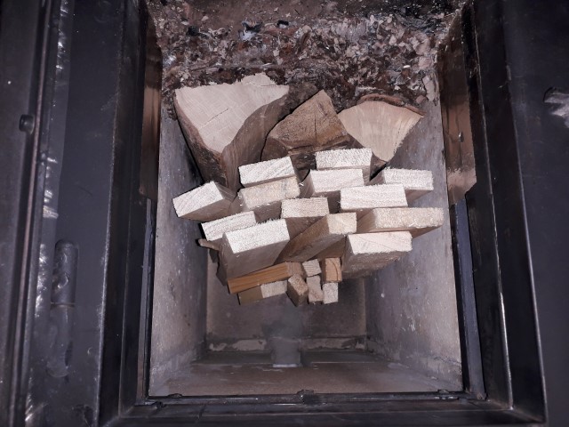 Four medium sized pieces were added on top of a glowing pile of coals, the CO line went up very steep, presumably I made the error to damp down all high flames with the fuel. Once I corrected that by opening up a space between the logs CO went down very steeply. From then on, results were very nice, see diagram below. 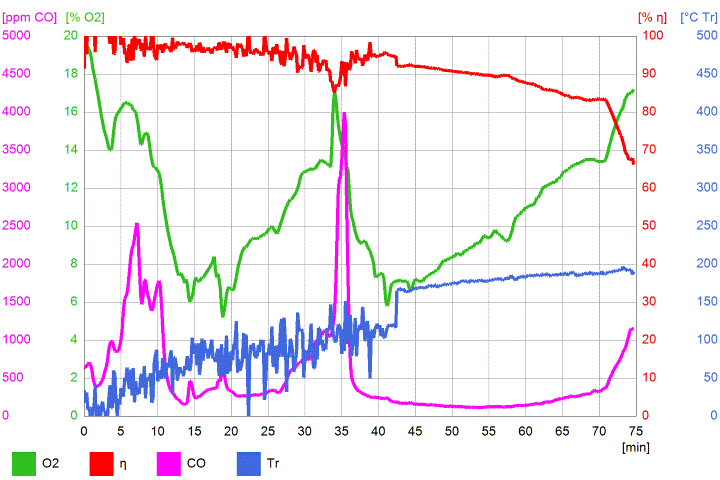 The flames in the firebox were looking good as well, as in the afterburner tube. 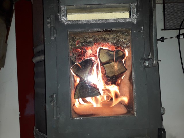 This core seems to lend itself perfectly for refilling now and then. All this is good, but the remarkable point here is the proportions of the afterburner area. Still assuming this is a 130 mm (5.12") system, the ceramic tube is 115% of system size, the port 50%, the end port 100% and the total space around the tube 158%! In numbers, no restriction at all, rather the opposite. Despite of that, the core didn't show any tendency to go into thermal runaway or overfuelling, judged by the diagram. Mind you, the picture below was taken *after* the first run, not before. It looks overly clean, not a black spot to be seen. What's more, the tube's parts still does show no cracks at all, however small. 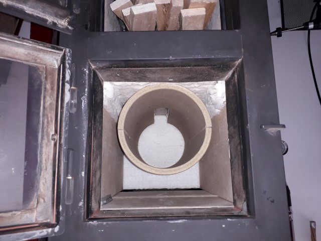 It seems I am getting close to a really stable heater core now, my next goal is designing a heater sporting a somewhat wider and lower firebox and top box. And, for the first time, have that produced by professionals and have it tested by an accredited lab. Interesting times! |
|
Forsythe
Full Member
   Instauratur Ruinae
Posts: 208
|
Post by Forsythe on Jul 12, 2021 7:51:40 GMT -8
First off, thank you enormously for your diligence in testing and R&D with these wood burners. Reading these forums has and continues to be an invaluable resource — saving me from making many costly design mistakes I would have otherwise stumbled into if I were doing this on my own from scratch with no guidance. Same goes for Trev/Vortex, Matt Walker, Donkey, Patamos, among many others here. I greatly appreciate all of your very generous sharing of knowledge in this community. A question, if I may, regarding the split cut along the ceramic cylinder’s length: The thicker one from Hart was split along its length and mounted horizontally in the development core. After fired for approximately two hours, running red hot at the far end and cooled down during the night this one showed two cracks in the top half. Both a little over 5" from the rear end left and right, roughly halfway above the port opening. I used this as an indication where the highest thermal stress would be. One thinner item from the same manufacturer was cut the same way and an extra cut was done at right angles over the top half, 5" from the rear end. Were these lengthwise cuts made to relieve the thermal expansion stress and prevent irregular cracks forming elsewhere in the cylinder’s circumference? And if so: did it work at preventing further cracking? I guess I’m just confused as to the sequence of events and thus what prompted the decision to place the cuts in those locations. You mentioned crack formation after firing and cooling some of them — but one of the manufacturers fabricated the tube for you with those cuts before you observed cracking in this location? Sorry for my confusion. Just trying to understand which cuts were made for what purpose. I’m about to cast a mold design using [rather expensive but extremely hardy] 94% alumina in a cylindrical shape for the primary burn chamber (fire box) similar to the Pyroclassic Fire’s design from NZ…but adding a viewing window into the upper afterburner, using a wider cooktop surface, and adding more mass before venting the exhaust up the chimney (ideas all taken piecemeal from various designs I’ve seen here.) Pyroclassic wraps their cylindrical ceramic cores in KaoWool, then bands the assembly in a stainless steel collar (with a flanged expansion joint where the ends of the collar come together.) This technique apparently allows for cracking in the ceramic core but holds the shape for at least 30+ years under moderate tension due to the collar and compressible ceramic fiber sandwiched between them. [Attempting to share images to explain that word-salad below] i.imgur.com/NkORpx3.jpg i.imgur.com/3tyi1it.jpg imgur.com/a/kXyv8ML If casting the cylinder in two halves [upper and lower] would prevent irregular cracking elsewhere, I may rethink this cylinder mold — and instead form the 12” internal diameter ceramic tube core in 2 separate pieces. (Cutting this 94% alumina ceramic after casting would be a nightmare, I’m sure.) Thanks again, and cheers, -Forsythe |
|
|
|
Post by peterberg on Jul 13, 2021 1:44:33 GMT -8
First off, thank you enormously for your diligence in testing and R&D with these wood burners. Reading these forums has and continues to be an invaluable resource — saving me from making many costly design mistakes I would have otherwise stumbled into if I were doing this on my own from scratch with no guidance. Hi Forsythe, welcome to the boards. Thank you for the compliments, glad to be of help. Were these lengthwise cuts made to relieve the thermal expansion stress and prevent irregular cracks forming elsewhere in the cylinder’s circumference? And if so: did it work at preventing further cracking? Yes, the sole purpose of these cuts were to prevent cracks. In fact, the cuts could be viewed as pre-cracks. The second tube from Hart Keramiks is still installed, no cracks to be seen so far. In total there have been 12 test runs with this part in place, rendering the far end of the tube cherry red, in and out. Seven of these burns have been full test runs using the Testo. I guess I’m just confused as to the sequence of events and thus what prompted the decision to place the cuts in those locations. You mentioned crack formation after firing and cooling some of them — but one of the manufacturers fabricated the tube for you with those cuts before you observed cracking in this location? Sorry for my confusion. Just trying to understand which cuts were made for what purpose. The manufacturer delivered the tubes cut to length, nothing else. The other cuts I did myself, using a small angle grinder and a diamond disk. Seeing all the runs so far with circular afterburner chambers it has been obvious that the hottest part happened to be the top half. This top half always were the first to burn clean after a cold startup, starting at the rear. I reasoned there would be a choice: doing the split horizontally or vertically. I chose the horizontal approach since those halfs could be layed on top of each other, holding together by gravity. Otherwise I would be forced to strap those halfs together in some way. After that first run, some smallish cracks appeared and based on those I decided it would be best to made the second cut right where those cracks showed. Reasoning that cracks mean there's tension in the material, having it devided in smaller pieces less tension would be building up. It's a process of reasoning and testing whether the theory would hold in practise, nothing else. It's a slow process, sometimes I'll get lucky and have it right in just a couple of tries. |
|
Forsythe
Full Member
   Instauratur Ruinae
Posts: 208
|
Post by Forsythe on Jul 13, 2021 12:56:03 GMT -8
Ah, I see. Thank you, Peter. That’s quite a clever way to manage what will likely be inevitable stress cracks due to thermal cycling. If this method continues to perform as well as it has, it would be a far more elegant solution than the banding collar assembly around a monolithic core of single-cast construction. Brilliant  |
|
|
|
Post by smartliketruck on Aug 21, 2021 22:40:37 GMT -8
Still assuming this is a 130 mm (5.12") system, the ceramic tube is 115% of system size, the port 50%, the end port 100% and the total space around the tube 158%! Catching up on this. It is hard to tell from the pictures, is the end port in the front of the secondary burn chamber above the window, or is it in the back end above the ceramic tube? I would have assumed still exiting the front but you noting the 158% of CSA around the tube has me doubting that. |
|