|
|
Post by peterberg on Feb 23, 2021 6:10:03 GMT -8
For your efficiency line, that's combustion efficiency, right? So if CO was zero, efficiency would be approaching 100%, as in, all burnable fuel is burned? Am I understanding this correctly? The red line is overall efficiency, which means it's the product of combustion and extraction efficiency. And it's lower heating value (LHV), quite common for Western Europe. Higher heating value (HHV) is 10% to 12% lower as compared to my numbers. The Masonry Heater Association did about 500 heater testings, while the overall efficiency on higher heating value rarely exceeded 80%. Our batchrocket numbers are mostly around that value or above, mostly due to lower end temp. That doesn't go for my development model since end temp is quite a bit higher. Efficiency calculation is done with end temperature and O² level only. CO doesn't play a role in that, it's a "flag" that indicates the quality of combustion. So your understanding of the process isn't really correct. |
|
|
|
Post by peterberg on Feb 23, 2021 6:32:55 GMT -8
So is the space above the horizontal riser stub is the same csa as the stub! No that isn't correct. The space above the riser tube is equal to the csa of a 120 mm circle, being the system size. The tube itself is 150 mm internal diameter, quite a bit larger than system size. If so perhaps two stacked stubs, one top of each other would work? Not likely, the restriction is there, but not by means of a smaller csa. It has something to do with part of the route being at a lower level, i.e. around the sides of the tube. Hot gases tend to stick to the higher level, they resist to follow a lower level route. No broken riser design. Just a thought: in the same space, the outer edge of the tube's upper half is 1.57 times the length as compared to a straight horizontal line. Which helps a lot to go around that 180º bend. It's all about shape and physics, in my humble opinion. |
|
|
|
Post by Vortex on Feb 23, 2021 8:06:09 GMT -8
More testing has been done. Notably, I have been at the lookout what aspect might trigger it into thermal runaway or fuel overload. And guess what, I found it. Yesterday I enlarged the space above and around the riser(?) tube up to 130% of system csa. Keep in mind, there isn't any stumble block or restricting end port at this moment. I loaded the thing with a normal batch of about 3 kg (6.5 lbs) and ran it. I expected there would be a fat chance for it to switch into overload, and it did. Today, I made provisions to adequately shrink the space above and around the tube down to just a tad over 100% of system size. I checked everything and loaded the thing again as the day before. Now it behaved quite differently, the O² went down to a level that most heaters would kick into smoking like mad. It's behaviour showed the 180º turn above the afterburner should be quite accurate. This burn appeared to be short and it was. Hard wood fuel is the next step to test this is viable as well. I found with my experiments this year, that increasing the inner surface area of the end port, or a more convoluted path for the gases improved stability better than a tighter restriction. Though I never thought of making the top chamber 1 CSA long and shallow to maximize the friction and do away with the stumbler and end port altogether. It seems from your results that resistance to flow from increased surface friction may work better than a restriction. I will try that out on my setup this evening. |
|
|
|
Post by peterberg on Feb 23, 2021 9:04:06 GMT -8
@trevor, the way my development model is configured now, the surface area is greatly increased, that's true. Whether or not you could mimic the same situation using your rectangular afterburner cross section remains to be seen. But that's what we do: experimenting until eternity and stumble upon solutions now and then, helped by experience which rules out a number of possibilities.
According to my calculations, in order to convert the rectangular scaled-down afterburner into a circular cross section it should be about 140 mm diameter in my case. What I have at hand was 150 mm so I tried that with remarkable results, I might add. The strange shape of the gas path over the tube was a happy coincidence.
Realising a very insulative afterburner tube following the 5-minutes riser trick would be doable for any reasonable handy human, I'd say.
Very curious what comes out of this increased surface friction idea implemented in your setup! In my view, a real restriction is posing friction on the higher volume that need to pass once the afterburner is hot. A lot of surface area would act as a restriction while the gas speed goes up, it feels really different.
Just random thoughts, sorry.
|
|
|
|
Post by Vortex on Feb 23, 2021 15:46:07 GMT -8
The run seems to have confirmed my theory, the conditions were not at all ideal and it performed admirably. I removed the stumbler and set it up so the first 8 inches/200mm back from the front of the shelf was 275mm x 63mm, just under 1 CSA, the end port I opened up to 120mm x 145mm, 1 CSA. The weather was 12.5C and blowing a gale outside, I didn't want to overheat the house so just did a 3/4 load. I didn't add enough kindling though and it started to crash so had to open the door and add more 10 minutes in - hence the large startup hump. It then settled into a nice long steady burn. The small hump in the middle was a piece of wood that fell down behind the primary air port which I had to move out the way. Thermocouple keeps dropping out because of a bad connection. I'll do a few more runs with the same configuration and see if the results are consistent.  |
|
|
|
Post by peterberg on Feb 24, 2021 13:02:10 GMT -8
Just an hour ago I completed the latest test. While the test was running, my lifelong dearest called: she asked me to bring her keys so she would be able to ride home on her bike. Long story short, I left all the lights on, the Testo running and the laptop recording the numbers but I had to close the door of the development stove. Coming back home in about 40 minutes the test was nearly completed, the resulting diagram shown below. 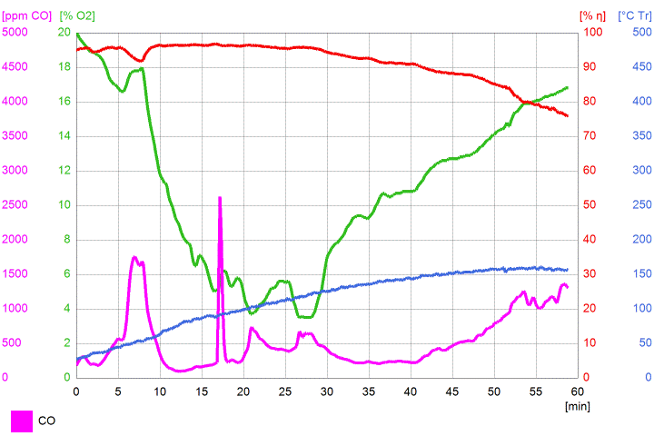 Not bad, not bad at all. The sharp peak in the CO line at 17 minutes occurred just 2 minutes after I left the thing running by its own. Judged by the look of it before I went out, a thermal runaway was imminent. Flames where coming over the edge of the tube literally everywhere. Apparently, the burn recovered real quickly after that sharp peak, producing very good results overall. This run was done with hardwood species, from a small stack of reasonably dry hornbeam bought specifically for this development stage. Not much wind, weight of fuel a meagre 3 kg total. Minimum O² 3.5%, CO 96 ppm. Averages of this run: O² 11.1%, eff. 91.5%, CO 539 ppm, temp 113.8 ºC. Normalizing the CO level to 13% O² would mean average was down to 460 ppm. Air distribution isn't finalized yet, there's more work to be done. |
|
|
|
Post by peterberg on Feb 26, 2021 12:46:13 GMT -8
Yesterday, I modified the air frame in such a way that the sides openings are shorter now, and opened up the top of the firebox' door frame. Main reason: it ran fine having the firebox door open a crack, but closing the door caused the CO to go up. This is just trying different air inlet proportions, fine tuning is still some time away. Anyway, here's the diagram from yesterday night. Door was open the usual crack to start with, after 10 minutes closed to just a fraction and at 17 minutes closed completely. The main air inlet has been full open all test runs, by the way. 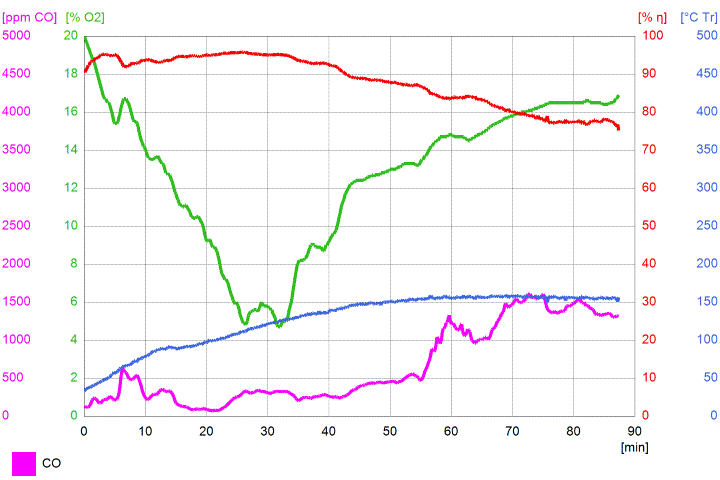 Fuel weight about 4 kg total, hornbeam, 17% moisture. At the time the O² appeared to be lowest, between 25 and 33 minutes, the flames were raging out of the afterburner. And by the look of it, I'd say a thermal overdrive was very likely. But it wasn't, this thing's function remained very, very stable. The tailout was a bit of a surprise being overly long because the CO² went down to 4% very slowly. Averages of this run: O² 12.8 %, eff 88.2 %, CO 659 ppm, temp 127.3 ºC. The run length is nice, the stretched out tailout isn't. I managed to shorten the tailout previously by adding a tiny amount of primary air at the back. Maybe I need to enlarge that a bit so the tailout won't be that long, 70 minutes for the entire run would be nice enough for such a small device in my opinion. |
|
|
|
Post by peterberg on Mar 18, 2021 9:52:34 GMT -8
I haven't been idle the past three weeks, far from that. About two weeks ago I changed the 15cm (6") stove pipe out for a 13cm (5.12"). Most dimensions of this development model are akin to that smaller size so I tried it. The behaviour of the stove changed quite a lot, it became much slower to start up, mid-burn not very fiercely plus a slow tail-out. In order to check whether or not the afterburner was oversized now, three days later I lined it with a single layer of 12 mm (0.5") superwool and ran it again. It looked good but came on very slow and the tailout long again.
After that I tried some other things and found out I miscalculated the space above the afterburner. It happened to be more like 85% of system csa. So I enlarged it upto 105% system csa. The end port, being 97%, is left unchanged. Height of the burn was more fierce then although coming up to temp still slow and a long tailout. Part of the problem seemed to be some larger fuel pieces on the ash bed that burned very slowly. All the above found out in about 10 testruns.
Yesterday I used two short steel bars, laying on top of the slanted sides of the firebox. The goal being to keep the fuel slightly above the ash bed. This seemed to work in the sense that the long tailout disappeared. At the same time, the small rear wall air supply was still open, so today I checked whether or not it would be obsolete now. The fuel was just pine lumber scraps, moderate portion, the rear air inlets plugged up. It worked, coming up to temperature was still slow and CO line was coming up and down in an irregular fashion. Tailout was relatively short as soon as most of the flames disappeared. Top of the burn eyed a lot better now, so progress have been made. The liner of the afterburner shrunk down in such a way that the internal diameter of it shifted to 13cm as well. So at present, I would say it's more like a 13cm system now, according to the standard batchrocket proportions.
Things to solve: shorter warm-up time, getting the air supply right.
|
|
|
|
Post by martyn on Mar 18, 2021 23:32:40 GMT -8
I commend your perseverance and i look forward to your final conclusions .
|
|
|
|
Post by peterberg on Mar 21, 2021 9:40:02 GMT -8
After more meddling with air inlets and fuel arrangements one question remains: what is the lowest level of oxygen this design could handle without sending the CO level sky-high? To this end, I opened up the end port to 113% of system's csa, opened up all air inlets slots including the one above the door and loaded the thing with small pieces of hornbeam on top of two steel bars. That last one was a tad more complicated than it sounds but I managed. With lots of air, high-energy fuel and relatively unrestricted exit, that would be a sure recipe to send the thing into thermal overdrive. And it did, unsurprisingly, although this state of affairs lasted for 7 minutes only. I had to restrain myself to let the thing go without trying to keep it within reasonable levels. Here's the diagram of this event. 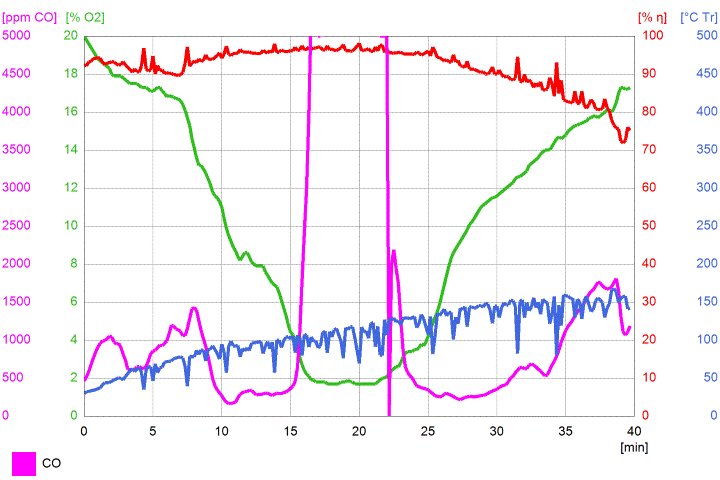 Startup wasn't slow at all, CO levels of start and end were reasonably low. It looks like this configuration can get unstable below 4% O². Incidentally, level of O² in a condensing natural gas boiler is kept at 4%, because... it can get unstable below that level. This run was done yesterday night so the neighbours couldn't see the smoke out of the chimney. Today I ran the thing again in the afternoon, but I've spent most of the morning to modify the core to a stable state. Brought back the 97% end port, blocked part of the top air slot in the air frame and made the venturi port slightly wider to be closer to 50% system csa. That last action because I noticed a slow pulse during the height of the burn yesterday. Fuel hornbeam again but smallish logs, 6 of those, and some kindling on top. Fuel weight: 4.2 kg (9.26 lbs). While starting up I kept the door open just a crevice and closed this around 8 minutes into the diagram. Interestingly enough, the burn did develop somewhat different to earlier test runs during which the door was kept open a generous crack for about half of the burn time. It might be possible that the thing won't like switching from door fed to air frame fed. I had to sit on my hands in order to mimic the certification test properly, after closing of the door. It isn't allowed to touch the thing while the official test is running, that's why. It looks like I won't come any closer to a good certification test than this one, see the diagram. 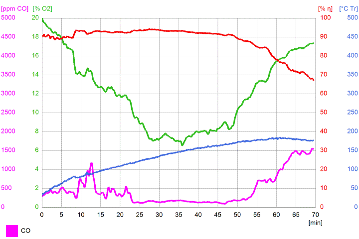 It's done by the book, even the end-of-test protocol of the EU norm is followed. Averages of this run: O² 12.1%, eff. 88.4%, CO 459 ppm, tr 134.7 ºC. No smoke to be seen during all of the burn, bar from a faint plume of water vapor which dissolved within a couple of meters in the air. Of course, some more test runs using the same configuration and fuel need to be done to check whether or not it was a one-off ideal run. Next goal: making some drawings for the final core design and do the design of the steel bell and door, chimney exit and air inlet box. Lots of work to do, no time to sink into lethargy. |
|
sbc84
New Member

Posts: 5
|
Post by sbc84 on Mar 26, 2021 6:53:49 GMT -8
Peter I am very excited to see this come to fruition as I am almost finished with my new shop and am looking forward to start building the heater for this building even though we are officially in spring here in Oklahoma with hot summer days just around the corner. Your hard work and love for tinkering, perfecting is very much appreciated.
|
|
|
|
Post by peterberg on Apr 6, 2021 3:04:40 GMT -8
Your hard work and love for tinkering, perfecting is very much appreciated. Muchas gracias, always glad people recognize the added value of this technology. This past two weeks I did 9 more testruns, despite Easter break. Using different fuels, and a multitude of circumstances. At some point I discovered a small leak between the air frame and the upper chamber and wondered if that made a real difference. So I implemented an intentional leak and the diagram below is the result. 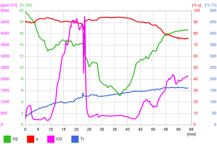 As can be seen, upto 10 minutes into the burn things went very well but further down the line CO rose and whatever I tried I couldn't get it down. At the same time, the afterburner eyed quite well, nothing wrong with that. While the burn commenced I drew the conclusion the CO was leaking through the air frame into the upper chamber through that narrow opening. Since it didn't start doing this before the air frame heated up this opening should be plugged. And I did around the 24 minutes mark in a couple of seconds and wearing welding gloves. As is clear after that action the CO took a steep dive and stayed low well into the tailout phase. Average numbers weren't that good, as expected, although reasonable given circumstances. So the next day I plugged the leak adequately, raised the area where the side air slits were covered to 10 cm (4") and repeated the run using the same fuel. This happened to be much, much better, well within specs and goals although still too wild and violent to my taste. 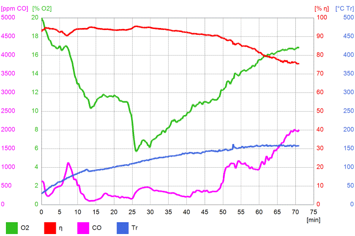 Some work need to be done still, in the mean time I checked the same configuration using hornbeam as a more energy-rich fuel. At the top of the burn it went haywire for about 2 minutes while the ogygen level dipped down to 2%(!) while this happened. After that was done all was well again. I have to add: during this latest run strong gusts of wind upto Bft8 were going so this might not be a representative situation. See the diagram below. 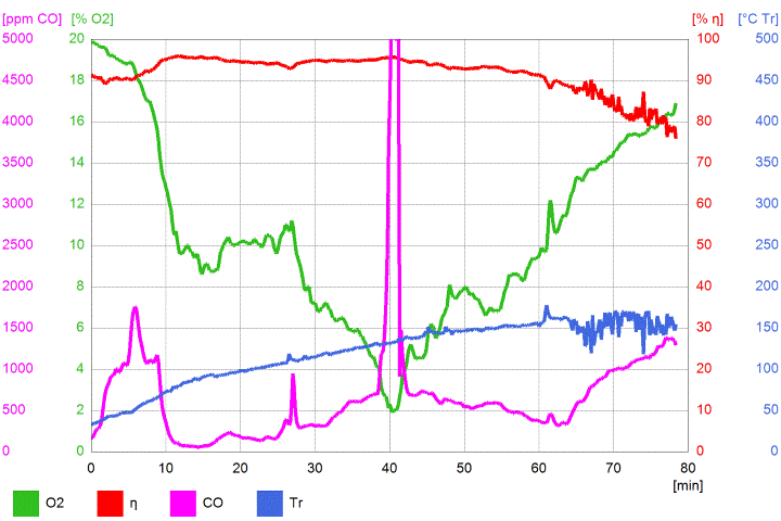 Conclusion sofar: this tiny (5") DSR1+ thingy is extremely tolerant to low O² levels, more so than the straight batchrocket. One might wonder how an upscaled item would behave since the larger ones tend to be much more stable, or so it seems uptil now. At the time in 2009, when I started meddling with wood combustion experiments this level seemed to be anything below 10%, J-tube experiments were down to 8%, batchrocket experiments went down again to 6% and now the instability level is below 4%! In the Netherlands, natural gas condensing boilers maintain a level of 4% O² as a minimum so this is quite an achievement I'd say. |
|
|
|
Post by peterberg on Apr 6, 2021 7:05:39 GMT -8
The next diagram shows what I said above, the O² level wasn't lower than 4% although the lowest point happened to be 4.1% so it's awfully close. 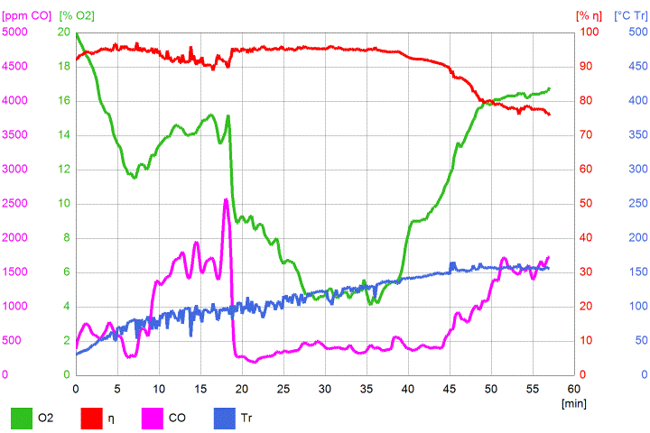 Same circumstances as yesterday with gusts of wind upto Bft8. Same fuel configuration as before, hornbeam and conifer a bit more softwood kindling which seemed to slow down fire development this time. The other difference is this: I left out the two steel bars that held the fuel above the ash layer. The development of the fire was just as violent after initial hiccup but as a whole the burn appeared to be very stable. Without these high winds the burn would be less violent coupled to a longer duration I'd say. |
|
|
|
Post by markuspad on Apr 13, 2021 1:30:25 GMT -8
Peter, I also just want to add that I am very excited to see the progress on the dsr1+ stove and that you are trying to get EU approval. I am planning to build a tiny house rmh, that can also be used for cooking, next year here in the EU and hope to be able to make use of your model.
|
|
|
|
Post by peterberg on Apr 15, 2021 6:04:09 GMT -8
Another short video of the development model, a very recent one this time around. Running on just 3.2 kg (7.05 lbs) of pine lumber scraps, duration of the burn from start to glowing phase around 50 minutes. It's filmed with a better camera than mine, the separate flames are visable all the time. The buzzing of the Testo is absent during this video, the burn was just for showing how it works.
|
|