Teach
Junior Member
 
Posts: 89
|
Post by Teach on Jan 2, 2010 16:06:34 GMT -8
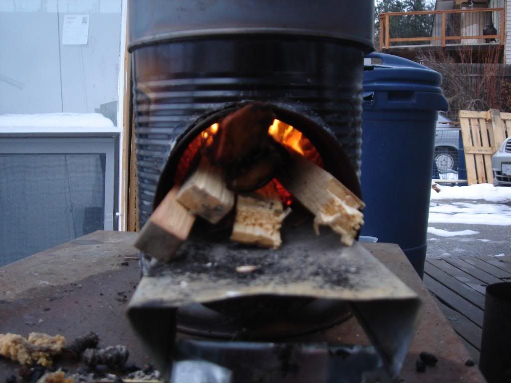
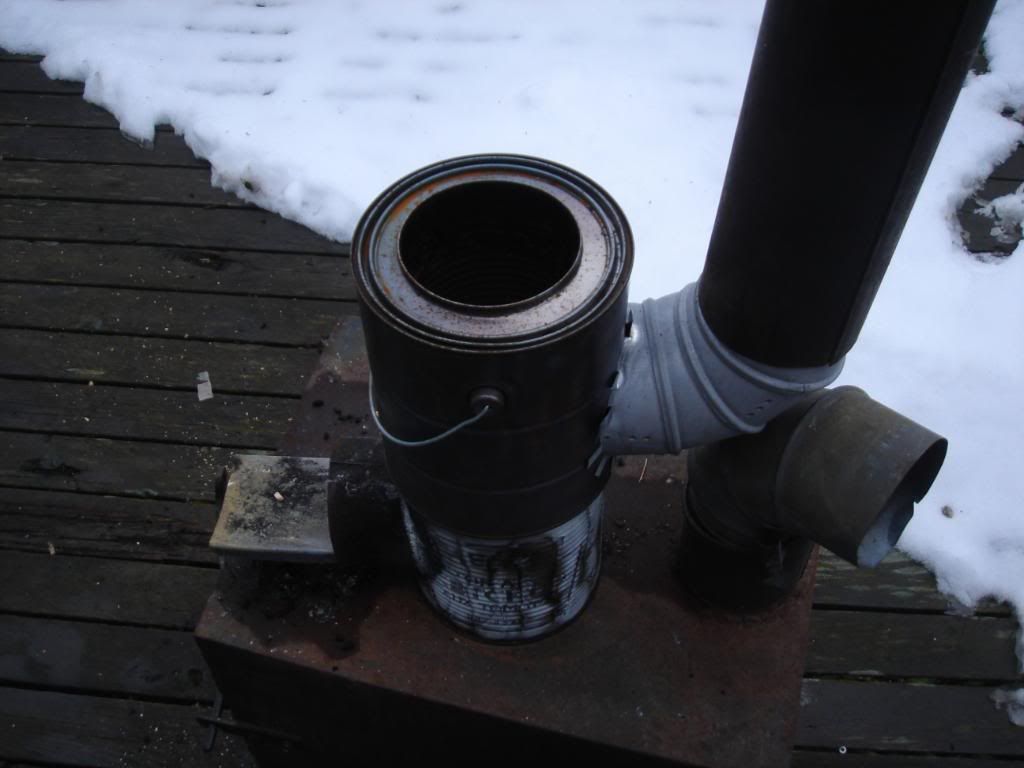
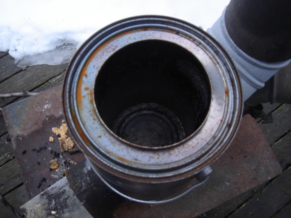
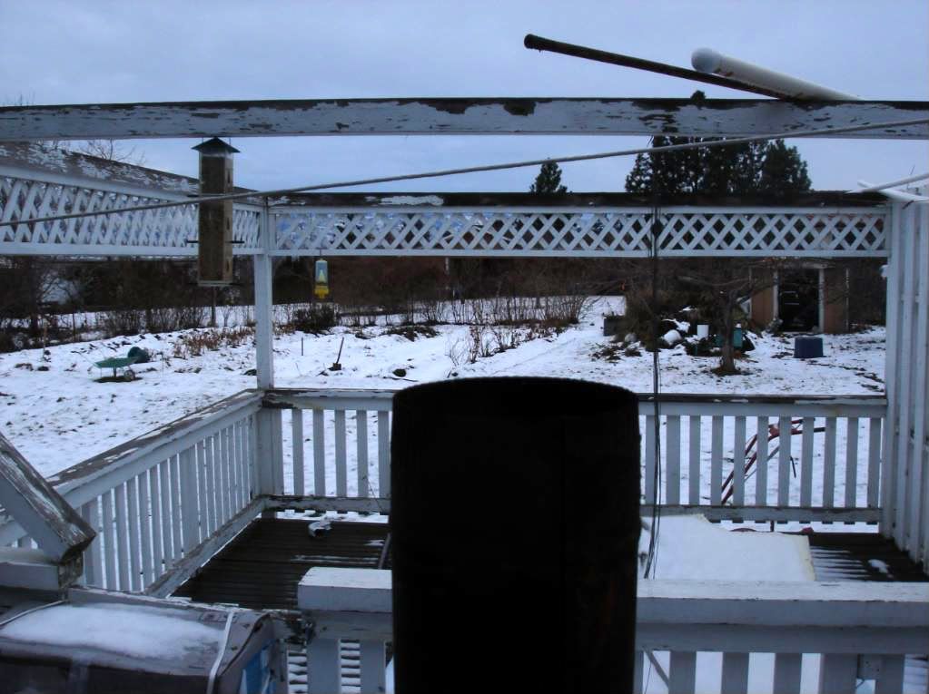
I put together a small rocket stove as an experiment for a heater in my garage which is 22x22 so I did not need much in the way of a heater as the garage is also insulated. The one I built is sitting on top of an old plain wood stove just to get it up off the ground for a more comfortable working height and keep it off the wooden deck in case it got too hot. The vermiculite worked very well at insulating the combution chamber. What I wanted to do was incorporate a small heat exchanger on top of the rocket stove that would pull more heat out of it and into the room. Initial results are promising even with my mistake of cutting the chimney exit hole at the bottom rather than at the top of the heat exchange. I had two designs in my mind at the time of the build and wouldn't you know it, I cut the hole in the wrong place. I did not even notice until I had the stove fired up and the bottom inside of the heat exchanger was red hot yet the sides one inch from the bottom of it were black not red. Thats when I realized what had happened and too much heat was being drawn off down low instead of up high where the hole should have been cut. Otherwise I think the upper section of the heat exchanger would have been much hotter. The other thing I noticed right off the bat was that the stovepipe elbow that I used did not function very well. The 90 degree corner should have square corners not round like the elbow had. It results in a poor accumulation of coals all up front with few under the burning fuel. Showing the combustion chamber;  Showing detail of the heat exchanger. It is a can with a bottom on it mounted inside a larger can. The inner can sits far enough above the exhaust of the rocket stove to allow the gasses to exit up and around the between the walls of the inner and outer can and then exit. This effectively doubles the surface area of the heat exchanger as per one of Aprovecho's ideas. I simply oriented it differently so it sits directly above the rocket stove.  Closer look at the top of the heat exchanger from above.  And finally one of the clean exhaust.  Well there you have it. I would love to hear back from all of you as to how I might improve this design. I was thinking of adding a series of heat exchangers but with this one alone, two feet up the chimney I could hold it with my bare hands so it is working well enough that I don't think additional ones are needed. I hope the file sizes are not too large....let me know. Ideas? Teach.... |
|
johnf
New Member

Posts: 18
|
Post by johnf on Jan 28, 2010 8:47:58 GMT -8
Very nice first experiment! I'd like to work on something about that size too, for small scale heating. Is your intake & flue about 4"? I might have thought that was too big a fire, and would get such a small HX (heat exchanger) all red hot (been too much for the size), but apparently you've got it balanced pretty well. I too have debated the down-draft HX versus the up-draft, and I'm pretty sure the up-draft is the way to go (the source of your flub during construction, I assume). One thing about the empty inner can, is that there's not actually much airflow through it. How about entry into the HX on one side near the bottom, exit the opposite side at top, with the entire inner can cut-out for airflow. One problem is working tolerances of joins, so it's tight enough to ensure draft through something so complicated, without leaking. This might especially be a problem with joining a flue pipe to the curved side-wall of the can. Possibly just cut-outs through the double-wall to allow some air flow through? I understand it's difficult to make a hybrid that works: If you tried to make one that'd be good for cooking, and have a good HX, it probably won't do either very well. One thing I'd like to try on something this scale is to make it with a hot plate at the immediate top of the fire, before it goes to the HX rather like this: <object width="425" height="344"><param name="movie" value="http://www.youtube.com/v/9M-4aUqa7RU&hl=en_US&fs=1&"></param><param name="allowFullScreen" value="true"></param><param name="allowscriptaccess" value="always"></param><embed src="http://www.youtube.com/v/9M-4aUqa7RU&hl=en_US&fs=1&" type="application/x-shockwave-flash" allowscriptaccess="always" allowfullscreen="true" width="425" height="344"></embed></object> www.youtube.com/watch?v=9M-4aUqa7RUScaled down to the gallon paint bucket. Enough for a pint of tea water or cup of soup or so. Do you think it would still have draft up through the top of the uptake pipe or would it be too cool by then? Suggestions for the top plate have varied from a cast-off cut-out flat from a cast iron griddle or similar cast iron, or any strong cook pot bottom cut out, to simple hardware store thick rolled steel. (Too thick for snips; the steel for cans won't hold up long at all.) |
|
|
|
Post by Donkey on Jan 28, 2010 12:28:50 GMT -8
Cool gizmo, interesting project.
If the heat exchanger had a larger volume, like the whole paint can, it might act more like a bell stove. The chimney at the bottom would then become a design element and it would distribute the available heat quite evenly. It's likely though that a bell might be tricky (or unworkable) at the smaller scale.
??
And yeah, the images are a bit uncomfortable for my dialup connection.
I like to keep it below 640 X 480
|
|
johnf
New Member

Posts: 18
|
Post by johnf on Feb 12, 2010 23:56:19 GMT -8
The draft area of the plenum between the inner & outer cans of the HX must match the area of the 4" inlet at the bottom. I'm thinking an insulated burn tube extension above this stove's burner would make an even more energetic flame at the top of the HX height. This effectively means a re-design of what we've got here, to have a larger outer plenum can for air flow space to match. (for a 1" layer all around the inner 4" tube (pack between this 4" and a 6" can with ash), an outer can of =~8.5" is needed. (and better materials at the top...) Here's an impressive demonstration of what a 4" rocket tube can do, and why they like longer burn tubes (even uninsulated, many diameters above the primary fire zone it's still combusting as energetically as the initial fire zone.) Skip ahead and observe the difference, between 4:00-4:15, to that after about 5:30+ www.youtube.com/watch?v=p0rywiPHZEwI do think you're right in that a larger volume right at the burn is needed. A square cross-section or some other way to allow enough airflow past the fuel & fire working space & convenient handling of the fire. Our cheap-a $$ sheet metal (food cans and such) is in for a short but energetic life-span. This metal will crumble, and anything like solder, galvanization, or aluminum is going to go away quickly. I've found that the measurements work out well if using a 3" dia vertical burn tube. The plenum space between a 4" and 6" can more than passes the entire 3". It also might be beneficial to look at the dimension generators for the real rocket stove sites online (detail for dimensions between a certain-size burn tube & its optimal height, versus the gaps between pot-skirt and a given size pot, and the height between the top of the burn tube and the bottom of the pot) I'm also wondering if cut pieces from ceramic tiles would work for the rocket elbow and maybe a flat liner for the surface directly atop the burn tube. Anything that's refractory to sustain the temperatures, that's easy to find and cut, but durable? Shower/floor tile? Or would you need to go to a furnace/stove supply store? |
|
Teach
Junior Member
 
Posts: 89
|
Post by Teach on Feb 15, 2010 11:48:39 GMT -8
Very nice first experiment! I'd like to work on something about that size too, for small scale heating. Is your intake & flue about 4"? I might have thought that was too big a fire, and would get such a small HX (heat exchanger) all red hot (been too much for the size), but apparently you've got it balanced pretty well. I too have debated the down-draft HX versus the up-draft, and I'm pretty sure the up-draft is the way to go (the source of your flub during construction, I assume). One thing about the empty inner can, is that there's not actually much airflow through it. How about entry into the HX on one side near the bottom, exit the opposite side at top, with the entire inner can cut-out for airflow. One problem is working tolerances of joins, so it's tight enough to ensure draft through something so complicated, without leaking. This might especially be a problem with joining a flue pipe to the curved side-wall of the can. Possibly just cut-outs through the double-wall to allow some air flow through? I understand it's difficult to make a hybrid that works: If you tried to make one that'd be good for cooking, and have a good HX, it probably won't do either very well. One thing I'd like to try on something this scale is to make it with a hot plate at the immediate top of the fire, before it goes to the HX rather like this: <object width="425" height="344"><param name="movie" value=" www.youtube.com/v/9M-4aUqa7RU&hl=en_US&fs=1&"></param><param name="allowFullScreen" value="true"></param><param name="allowscriptaccess" value="always"></param><embed src=" www.youtube.com/v/9M-4aUqa7RU&hl=en_US&fs=1&" type="application/x-shockwave-flash" allowscriptaccess="always" allowfullscreen="true" width="425" height="344"></embed></object> www.youtube.com/watch?v=9M-4aUqa7RUScaled down to the gallon paint bucket. Enough for a pint of tea water or cup of soup or so. Do you think it would still have draft up through the top of the uptake pipe or would it be too cool by then? Suggestions for the top plate have varied from a cast-off cut-out flat from a cast iron griddle or similar cast iron, or any strong cook pot bottom cut out, to simple hardware store thick rolled steel. (Too thick for snips; the steel for cans won't hold up long at all.) Thanks John, yes it is a 4 inch system through and through. Originally it started as a side feed as shown in the pics but I also tried the down feed and much prefer the down feed as it negates having to fiddle with the fire so much. I had also had thoughts about the lack of air flow in the inner can of the heat exchanger but it would have really complicated the design and there is only so much you can do with a tin can especially with my tinsmithing skills........LOL I did not build this project to have any real lasting ability as the stove pipe and cans will burn out quickly. It was entirely to prove out an idea I had for a larger 8 inch system with a conventional RMH but with HE on top of the main barrel instead of to the side. |
|
Teach
Junior Member
 
Posts: 89
|
Post by Teach on Feb 15, 2010 12:27:44 GMT -8
Cool gizmo, interesting project. If the heat exchanger had a larger volume, like the whole paint can, it might act more like a bell stove. The chimney at the bottom would then become a design element and it would distribute the available heat quite evenly. It's likely though that a bell might be tricky (or unworkable) at the smaller scale. ?? And yeah, the images are a bit uncomfortable for my dialup connection. I like to keep it below 640 X 480 Hows it goin Donkey? Funny you mention that as the bell configuration is what I originally had, hence the exit pipe at the bottom of the HE. Of course there was no inner can with that set up.......only the 4 inch stove pipe that came all the way to within a 1/2 inch or so of the inside bottom of the "bell" can. It worked well and drafted well. I very affectively heated a kettle and I could have a full rolling boil in a short time so it could be used for cooking also in that configuration. Basically it was just a smaller version of a regular RMH barrel. When I changed that out and went with the inner can set up I could notice a fair amount more heat coming off the top of the heat exchanger. It made if difficult to hold my hand where I could hold it above the bell configuration. A hybrid as Johnb put it really isn't anything difficult to make work and I think we are going to be seeing much more joining of these two technologies in the future. One being of clean hot burn and the other being the recovery of that heat into the room or storage material before it exits the chimney. One thing I noticed is that a bell set up needs to have a much larger volume to affectively transfer the heat to the room.......otherwise in a smaller set up like the first version the heat is simply not in contact with the HE long enough to affectively transfer it's heat before it exits out the chimney. |
|
johnf
New Member

Posts: 18
|
Post by johnf on Feb 21, 2010 6:33:28 GMT -8
Sort of what I'm trying for. I've started and aborted a couple of times: figuring out how to join sections is tricky. I'm startiing with paper & cardboard to figure out the shapes to cut and how to jon them.  A buddy suggested trying to mix the air in with the "vortex" generating slits instead of plain holes. Make cuts at 45 degrees, and score & bend larger semi-circular shapes around from end-end. Use a torch and heat the semi-circles and tap/stretch them out into a form, to make cups to catch air from the pre-heating plenum, and direct it smoothly into the tube. Encourage it to turn up and spin around to mix fuel & air, and keep it away from the sides, to avoid losing heat in the mix. (the sides are insulated, and at this poiint, you don't want it to give heat away.) Inlet air to the plenum from a side to encourage the rotation of the updraft, and it might be worthwhile to do the same for the exhaust at the top. Force the air to spend the maximum amount of time to pick up heat at the bottom for primary, and at the top of the burn for secondary air inlet. Alternately, and maybe simpler, is to have a gap between the outer skin of the HX and the top of the outer skin of the burner body. Instead of exhausting through the sideways pipe, just let it out the bottom/outer skin of the HX. With the lid off for starting, it's a straight draft up through the burn tube, from the ash door. Make the pot rests and the outer skin of the HX the same height, and the bottom of a pot will seal against the outer skin, and it'll still exhaust under the HX. The lid might need to be fairly stout to take the heat. Food can metal might not last long. There's the requisite gap between the top of the upper insulated burn tube and the lid. In this gap on top of the insulation fill layer are the pot rests for cooking, and maybe supporting the lid with the same proper stand-off. Fuel inlet is also via the top lid removal. The grid of wire is between the top of the underneath ash sump, and the burn chamber with the inlet hole/slits. Theoretically, I'll build a nest of tinder/kindling from the top, and insert a torch under the grid in the ash sump. At first, I expect to need to keep the ash door open to facilitate air movement, but after the tube heats up and it starts drafting, I expect (hope) that it'll draft in through the plenum & slits on its own. |
|
Teach
Junior Member
 
Posts: 89
|
Post by Teach on Feb 22, 2010 9:55:22 GMT -8
Hi John, the first thing I notice is......one of the whole premises of these rocket stoves is that air is brought in from below the fuel and fire so that the air is not only surrounding the burn but also serves to preheat the air before it is encorporated into the burn. By having your cold air input above the fire I think it may cool down the gasses enough to affect the burning of them completely. Also, when your air intake is open you will have lost most of your draw to the bottom where it is feeding the flames and coals. The better the draw, the more air is sucked into the fire........the more air in the fire the faster the fuel burns........the faster the fuel burns the more heat is put out.
I like the upper section idea to combine the use of a pot or not option. But in order to pull off gasses to the side exit pipe from around the pot you will need a very snug fit from the pot skirt to the pot.....otherwise it will take the path of least resistance and may by pass the chimney altogether. You could encorporate your ideas into an institutional rocket cook stove from aprovecho and have pretty much the same thing without reinventing the wheel.
Good luck though. It's fun playin with this stuff isn't it!
|
|


