|
|
Post by peterberg on Jan 4, 2010 11:47:04 GMT -8
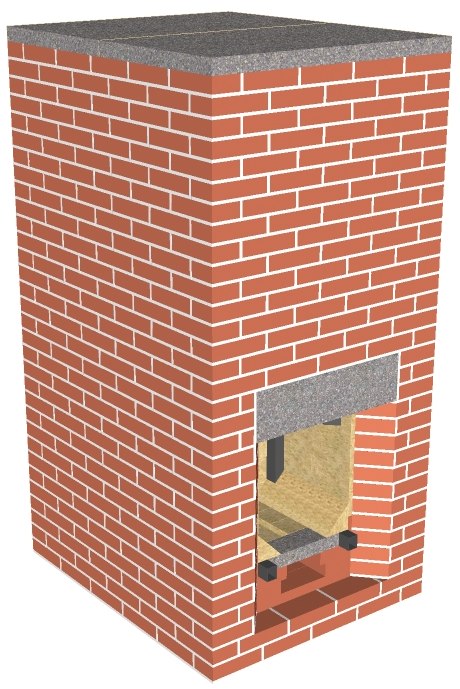
Another possibility: pberg0.home.xs4all.nl//pictures/PD/RB-PD5.skp The firebox/syphon combination inside a single-walled single bell. Its size isn't much smaller, but the weight is less compared to its double bell brother. Warming up is quicker, due to the single wall. Construction is simpler with the exit at the rear, at floor level. Exit could be alternatively situated in one of the sides. |
|
joris
New Member

Posts: 2
|
Post by joris on Jan 28, 2010 14:28:51 GMT -8
A have been studying the rocket stove principel and the ideas from Kuznetov for some days now. I have a question about your rocket/ bell.
The crevice from 10mm is this like the dry joint from Kuznetov, to get rid of the balast gasses in order to have a higher combustion temperature in the burning chamber? And why is it situated there? could it also be situated lower?
Do you use the J curve to get more turbulence? I read in a artical of Kuznetov: "If we supply air into the top portion of the firebox, it will be pushed down against direction of hot gas flow as being lighter in the hot gases environment" and he says that this causes turbulence. Is it better to have turbulence in the upper part of te combustion and is this the reason for the J tube?
And the last question in wich aspects is your stove superior to Kuzntovs?
Thank you
|
|
|
|
Post by peterberg on Jan 30, 2010 9:53:57 GMT -8
joris, The crevice was accidental at first. Later on I'd realized the chimney stack warmed up quicker with this slit open. However, it isn't necessary anymore because I've changed the construction slightly to reach the same effect. Of the seven prototypes, 5 were equipped with dry joints, Kuznetsov style. None of them showed a difference whether the crevices were open or closed. I do suspect it's only a nice theory. Alex Chernov, the man who's building double bells in Canada, couldn't find a difference either with testing equipment. About turbulence: in fact I'm using the rocket J-tube (or syphon) as an afterburner. Initial pyrolysis takes place in the fire box, unburned gases and tars are combusted in the syphon. This takes place because of two reasons: the downwards movement of the flames is causing a lot of turbulence, and because of the side-air tubes the temperature is really high in there. Much higher than required for spontaneous combustion of carbon monoxide and most of the tar components. Level of temperature is often between 900 and 1000 C., which is roughly between 1650 and 1830 F. The top part of the fire box is always higher in temp than the lower part, because the air is coming in there. And the hottest gases are in the top part anyway. The side-air tubes are different because the vertical part of the tubes do become quite hot and as such inject hot air into the flames. Level of temp there: readings of the hottest moment inside the tube did show 400 C., equivalent to 750 F. Your last question is a tough one. Honestly, I don't know whether my system is better compared to Kuznetsov's or not. The only thing I do know is this: the only way to be sure about anything is measuring. That's what I did with my setup, I don't know what results would come off Kuznetsov's.
|
|
|
|
Post by peterberg on Feb 1, 2010 12:25:10 GMT -8
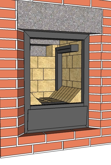
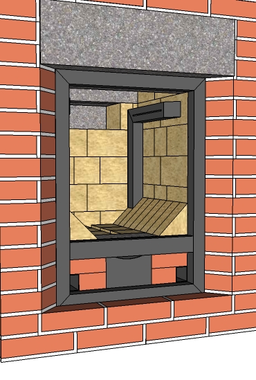
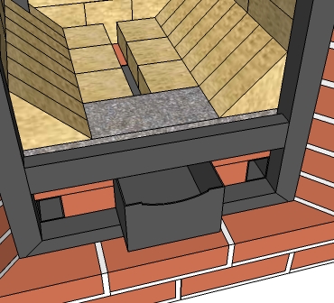
Finally, I've been able to incorporate the air intakes and door frame into the drawings. Both of the completed drawings are here: pberg0.home.xs4all.nl//pictures/PD/RB-PD4a.skppberg0.home.xs4all.nl//pictures/PD/RB-PD5a.skpA single ash door facilitates all three air intakes, the door opens only 5 degrees. This is an opening of 60 cm2, or 9.3 square inches.  That size is sufficient for this setup, after heating up of the chimney stack it could be smaller due to increased draft.  The vertical part of the side-air tubes is increased 4 inches in order to position the intakes as low as possible. There's an ash pan with a small opening to get under air via the opening in the fire box floor. This opening has to be high up, otherwise it needed to be much smaller. The reason is this: ambient air temp is ice cold compared to the fire box environment. So the air "splash" down immediately and is streaming relatively easy through openings at the lowest level. That would be the side-air tubes in this case. Secondary or "over air" do come in via a narrow slit the full width of the fire box, just behind the door.  The loading door isn't drawn, that could be anything from a frame made of T-profiles with glass in it to a single plate with a piece of castable refractory on the inside. In the door itself there should be no other air intakes. All the intakes do have the correct dimensions compared to each other. Opening the ash door further will create a greater emphasis on the front air, sliding the ash pan out over the available 40 mm or 1.57 inches shift the emphasis to the under air. That last one is tricky, because the fire will increase and the pollution as well. Not advisable I would think. Of course it's possible to weld the ash box to the ash door. In that case there's the need of a plate a little more than 2 inches further into the ash pan to restrict the air intake. The hinges of the ash door aren't necessary in that layout. |
|
|
|
Post by endrunner on Feb 1, 2010 21:55:12 GMT -8
Did you give any thought to the idea of bringing air in from outside? It seems it might help make the fire affect even more efficent by not sucking cold air in the rest of the house from the negative pressure of the rocket stove.
Also do you know if there would be any particular disadvantage to using cast refactory for the combustion chamber, rather than bricks, or using a stone and insulating blanket combo?
|
|
|
|
Post by peterberg on Feb 2, 2010 12:36:48 GMT -8
endrunner, There's much discussion about outside air. It's colder and will make the fire less efficient by cooling it down. It is open to debate whether or not it will prevent smoke spill in the inhabited space. And yes, there's a possibility to provide outside air. Not incorporated in this design, but it can be done relatively easy. Castable refractory is quite nice for a firebox. It will insulate a bit more than brick and as such do make higher temps possible. Stone (soapstone aside) isn't right for high temps, but materials like vermiculite board or the like do work. How long it will last, I don't know.
|
|
joris
New Member

Posts: 2
|
Post by joris on Feb 3, 2010 7:40:43 GMT -8
Is it then not possible to lead the air from outside through the bell to heat up first?
|
|
|
|
Post by Donkey on Feb 3, 2010 9:02:18 GMT -8
Is it then not possible to lead the air from outside through the bell to heat up first? Of course it is. It would be fairly simple to modify Peter's system to bring in outside air and pre-heat it. There would be some trade-off involved. |
|
|
|
Post by endrunner on Feb 3, 2010 22:06:36 GMT -8
I was wondering if you think the syphon tunnel would work equally well if it was pointed down rather than up. I was interested in incorporating a hearth/ledge/bench area below the heater as a large bell. Somewhat like your bench in your early versions.
Also from the pictures it appears you are using copper pipe, is this true? would steel be an option? The ends of the pipe look silver?
In the version where you were using the refractory cast from the commercial supplier, were the side walls still 270? Do you feel that the fire box core needs to be issolated by an air gap and a shell if thick insulated refractory is used instead of fire brick?
You also mentioned ...
"Provided around the door opening the aformentioned felt is used."
What is the aforementioned felt? Any details on the door would be nice. Commercial doors are crazy expensive. the special wood stove glass only on the other hand is doable.
thanks for your continued updates?
|
|
|
|
Post by peterberg on Feb 4, 2010 10:03:49 GMT -8
endrunner, The heat riser has to be upright, otherwise there won't be a temperature difference which is necessary to get the thing going. Maybe it could be done with a fan but I've got no experience of that. It's perfectly possible to have a bench lower than the firebox/syphon combination. Yes, I've been using copper pipe, and also thin-walled steel pipe. That's the one that look like silver. So in the drawings you'll find a tube of steel for the side-air. It's not strictly needed to insulate the fire box. In fact, I didn't, the refractory castable of the last incarnation isn't either. The stove is double-walled around the firebox and syphon, though. Insulation around the hottest parts could be helping to heat the thing up quicker. But what do you mean by 270? The felt I was referring to is aluminum silicate blanket, sometimes called Superwool. I have to think about the door, but because there are no air inlets in there it's a pretty simple construction.
|
|
|
|
Post by endrunner on Feb 19, 2010 19:09:18 GMT -8
Then do you think it would work if after the upward burn chamber the gases were routed down via refactory insulated duct to keep as much of the heat as possible until it hit the duct work at the bench level?
|
|
|
|
Post by peterberg on Feb 20, 2010 6:53:30 GMT -8
endrunner, What will be the difference in level from the bottom of the rocket down to the ductwork?
|
|
|
|
Post by endrunner on Mar 2, 2010 21:14:41 GMT -8
What I am thinking about doing is using a rocket stove as backup heat for my hot water tank. I plan to use solar hot water collectors, but we get a lot of rain, so I would like to boost my tank temperatures with a rocket stove, if the solar is not keeping up.
So my thought was to run exhaust channels underneat the hotwater tank. The exhaust channels would be square rather than round to maximise heat transfer to the water tank above, but embedded in cob foundation. So basically instead of a heated cob bench I want to heat my water tank.
The water tank would be say 4 ft x 8ft x 4ft high, burried in the ground.
I want to get as much heat as possible routed down under the tank and not going up into air. So I was wondering if I could insulate it enough until it hits the underwater channels.
Maybe it would take a small fan. I would prefer not, but...
Any ideas would be helpful
|
|
|
|
Post by ytksgmt on Apr 6, 2010 11:52:56 GMT -8
I tried to analyze the mechanism of RMH.
I studied physics decades ago and didn't used it in my daily life.
So, I can't be confident.
I don't speak English, and never write English.
So, I'm afraid I can't explain properly.
But,I'll try.
RMH is consisted with Riser and Downer.
Heat Exchange Barrel is equivalent to Downer Pipe.
In Downer part, part of heat is emitted.
The height of heat release center depends on the system.
For example, in barrel system, large part of heat is emitted from top surface of barrel.
So, heat release height gets closer to the height of Downer.
If you insulate upper half of Downer, release height get lower.
I applied a very simple model.
(May be, too much simplified to appropriate.)
Downer part is mostly insulated.
In a very thin area at height of JE, all the heat which should be emitted from Downer would be emitted.
Set Tr,Td,Ta the temperatures(K) of air in Riser, in bottom of Downer, and open air, each.
Set Rr,Rd,Ta the densities of each air.
Now, set parameter u = (Rd-Rr)/(Ra-Rr)
While Rd varies from Rr to Ra, u varies 0 to 1.
Density is reverse equivalent of Temperature(K).
That is, if heat release from Downer is large,
then Td (Downer Bottom Air Temp) nears to Ta (Open Air Temp), Rd to Ra, and, u to 1.
If heat release at Downer is small, then Td nears to Tr (Riser Air Temp), Rd to Rr, and, u to 0.
So, u represents the efficiency of heat release of Downer.
After several calculations I reached the condition for Drafting.
u > (J-H)/JE
Say, Riser Length H = 1m, Downer Length J = 2m.
And, Downer is heavily insulated ,resulting JE < 1m.
Then, right part of the Inequality is larger than 1.
But u must be less than 1.
So, the Inequality can't be approved.
That means the RMT can't work.
In this case, Downer's upper part above the release height is larger than Riser.
And the temperature of the part is the same as that of Riser.
So, the stack effect in Downer is larger than that of Riser.
Downer is no more Downer.
It's better to be called RISER.
RMH's drive engine is NOT the stack effect in Riser alone.
It's the difference of the stack effects in Riser and Downer.
If you want more draft, you can get it by cooling Downer.
If you want exhaust heat reached deeper, you have to cool Downer
more effectively and/or cool it at higher position.
|
|
|
|
Post by Donkey on Apr 6, 2010 16:40:15 GMT -8
Interesting..
I no longer think that stack effect is the main driver in rocket stoves. The reality never seems to fit the numbers. I have come to think that back pressure from expansion against the pipe is adding energy to the system (That is a clumsy way of describing it). I think that effect will allow the stove to work even when temperatures are equal in "riser" AND "downer".
I would very much like to find out the reality of these suppositions.
What you have outlined here is a testable proposition. I would very much like to see results on this.
Are you willing to do this testing and post your results here?
Also, I think this should have it's own thread. With your permission I would like to move it.
|
|