|
|
Post by peterberg on May 19, 2009 12:49:34 GMT -8
Hi all, For all development before May 2009, please see donkey32.proboards.com/index.cgi?board=experiment&action=display&thread=40I have spent a lot of my spare time trying to simplify the rocket syphon. In fact, the majority of my experiments has been in vain: at the moment I'm back to square one, more or less. In an attempt to make a very compact layout I've been testing a rocket syphon on top of the firebox. No good at all, it refused to work properly, whatever layout didn't matter. Two months down the drain and no results until two weeks ago. The syphon at the moment is made of refractory concrete, very thin-walled at one inch. The riser is short, twice the main opening plus a burn tunnel of one inch. Main opening is 4" by 8". 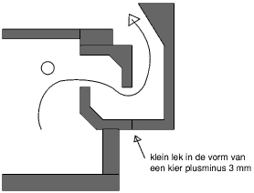 The riser is made of vermiculite board and is heated up in a very short time. As visible in the drawing, the air pipes are not just in front of the main mouth but 4 inches away from it. The layout of the stove itself is like this: 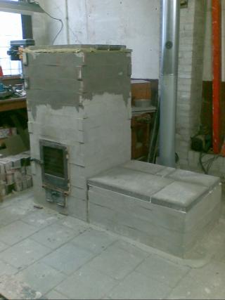 The bench beside it is nearly entirely hollow, first running 3 feet from the main stove and then about 2 feet back. At the picture the stove is 14 layers high, but now it is down to 11 layers. In order to make the parts of the syphon I've assembled a simple vibrating table. 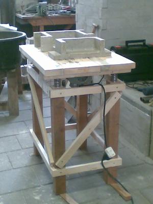 Two weeks ago I started with optimizing the burn. The results are very encouraging: the thing is running better now with less wood than last October. The pipes inside the firebox are lengthened with a piece that's running back to the door at the same wall. The horizontal piece has a thin slit of about 1/8" x 5 1/2". 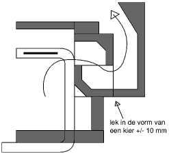 The slit is about half the surface area as the inside of the pipe. With minimal air fed through the loading door this runs remarkably well. 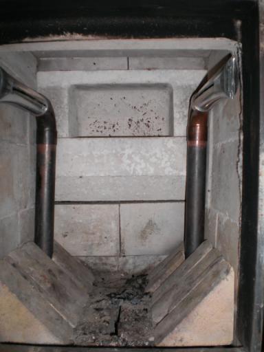 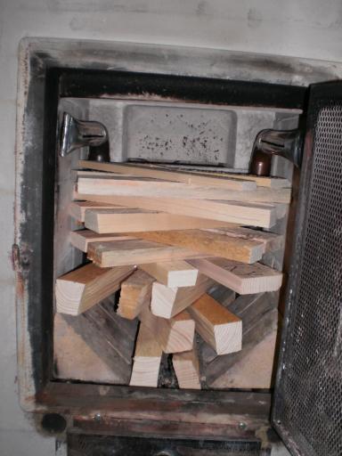 For performance, see graph: pberg0.home.xs4all.nl//pictures/large/test090516.gifExhaust temp is in Celsius, highest point 212 F. The workshop is being a bit of a mess, with too many pieces of material and tools laying around. 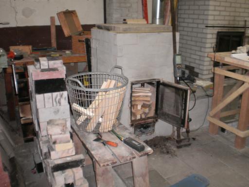 I've tried to take pictures of a burning stove, but that's only disappointing. Last week I've got a new camera which is capable of taking short films. Two of that I've uploaded to YouTube. The first is of the stove burning just before the height of the run. The flames which are blowing away from the pipes can be clearly seen. The second is at the end of the test-run after the second refill. The mouth of the syphon is a lighter orange than the firebox walls itself. Highest temperature just behind the second vertical wall of the syphon during the run: 1790 Fahrenheit. In fact, it's not the spot with the highest temp of the whole contraption. But the sensor is only capable of measuring up to 1830 F. Any higher and the thing will die quietly. Next goal: upscaling to 1.7 times and using the mantle and door of a commercial Bergkachel version. |
|
|
|
Post by canyon on May 19, 2009 23:09:09 GMT -8
Peterberg, Thank you for the update, I was sure waiting to hear the latest. Sorry to hear of the two month error part of trail and error testing. It is one of the prices to pay occasionally as an inventor/innovator. Is it safe to assume that the siphon exits into a bell? Does the exhaust then pass trough the bench? Are you testing for CO as well?d Thanks again for sharing your experience!  |
|
|
|
Post by peterberg on May 21, 2009 0:53:02 GMT -8
The syphon exits at the height of 2' 3" into the bell above it. At three sides around the firebox there's quite a lot of room as well. The exit of the first bell is at ground level, right hand side.
The bench is divided into two compartments, the one at the front the largest. Measuring 3' x 1' 4" x 1' 2", exits at ground level again at right hand rear side. The rear part of the bench is roughly half the size of the front one. Actually, the whole system consists of three bells. Looks quite small, but it'll capture a surprisingly large proportion of the produced heat. The bypass at the rear is absolutely necessary, otherwise the thing will not start at all 3 out of 4 times.
The rocket syphon and the exhaust isn't any larger than a 6" rocket/bench system Evans-style.
The bench on its own is equal to a 6" bench with a length of 35 feet. Calculated as cubic measure, of course.
Speaking about mass on the other hand, the two systems are not comparable at all. A normal bench system weights easily in at 5 times or more. But mass wasn't the goal I was after, it can be added easily later on.
And yes, CO is tested as well. Actually, it is one of the main factors to be reckoned with while tuning the thing.
What I did: keeping the CO and O2 as low as possible and maintaining a high output temperature at the same time. That last one is easy: everyone do want to have that.
A low CO level is increasingly difficult to achieve with low O2 at the same time.
The less air is sucked in, the volume that has to be warmed up is lower. This will result in higher top temps. Carbon monoxide is fuel as well, the process of decay to CO2 is producing heat. To combust CO, a high temp is necessary together with turbulence and a very precise air injection.
It looks like the J-shaped rocket stove has a large surplus of air sucked in. As long as that factor is not compromising the temperature too much, it'll work surprisingly well.
|
|
|
|
Post by northland on Jun 4, 2009 12:32:46 GMT -8
Hi Peterberg. This is my first post, but I have been following your progress for a while. Many thanks for sharing your work. I am very interested in your design, and hope that you will post specs of the final project so that others can build it. I built a rocket stove out of bricks in my back yard and used it for cooking on for several months after an avalanche took out the electrical lines connecting our town to its main source of power. I have since been looking for a easy to build mass heater for inside use. I don't have a shop to test things, but often thought of mixing a rocket stove with a traditional masonry heater. I also contemplated building a small mass heater of castable refractory cement, a design similar to that posted on www.envisioneer.net/main.htm. My only issue is that I am required by local ordinance to have only UL listed stoves or masonry stoves that follow the ASTM E 1602 specifications. That is why I am so interested in your design, as I believe it meets (or can be modified to meet) the ASTM E 1602 specifications. Is there anyway I can contact you to discuss this further? Thanks again for posting your research. |
|
|
|
Post by peterberg on Jun 6, 2009 1:54:56 GMT -8
My only issue is that I am required by local ordinance to have only UL listed stoves or masonry stoves that follow the ASTM E 1602 specifications. That is why I am so interested in your design, as I believe it meets (or can be modified to meet) the ASTM E 1602 specifications. Is there anyway I can contact you to discuss this further? Thanks again for posting your research. Where are you located? Somewhere in a mountainous region I would say, because of the avalanche. Today I've learned about ASTM E rules, and I would think my design quite possibly would comply with that. I don't know for sure until the proper measurement has been done. The small mass heater made of concrete pavers will not last long, I would think. Unless the firebox and the subsequent chambers are made of refractory castable. The air intakes are not specified, so every stove will have a different output of efficiency and pollution. |
|
|
|
Post by northland on Jun 8, 2009 14:26:12 GMT -8
Hi Peterberg.
Thanks for the reply. I live in Juneau, Alaska. The only access to my town is by airplane or boat. We are surrounded by tall mountains and an ice field on three sides, and the Pacific ocean on the other side (hence travel can only be by boat or plane.) I am fortunate to live in the capital of our state, which means that we are the commerce "hub" for this area. Alaska Marine Lines has an office here, which means that I can get stuff barged up from Seattle, Washington if needed.
The small mass heater I linked to only has air intakes through the door (which is made from steel.) I liked the design as it was something I could make, but I was thinking about making the entire stove out of dense castable refractory (like mizzou,) and incorporating some clean outs. I was thinking about using castable refractory as I was concerned about the concrete not lasting very long, but the original poster has not had any problems. I contacted him and he said the only issues he has had was with cracking on the back slab's exterior joints, and cleaning access. He said that he resolved the cracking issue with some high temperature silicone sealant. -Perhaps thickening the back slab thickness would help in this regard.
However, as I stated earlier I need to be able to meet ASTM E 1602, and I think I would rather go with a design that has had some performance testing. It looks like you are quite proficient at stove design and testing, and some of your smaller prototypes seem to be about the size I am looking for. I like to build things with my own two hands, as it helps me understand how things work, and helps me help others. I am hoping to find plans for a small mass heater that I can build.
Many thanks once again for posting your tests.
|
|
|
|
Post by peterberg on Nov 2, 2009 12:35:37 GMT -8
Hi all, Results of two major experiments are available now. The first one did consist of a single bell wider than deep, ratio W x D = 5 x 3. The firebox inside had have the same proportions as before, namely 1' x 1' and 10" from the firebox' floor to the edge of the throat. The rocket syphon was a different story: I've been testing an old idea about a double burn tunnel and heat riser setup. Please don't try this at home, it won't work properly. One of the risers would warm up first, at random left or right. That one performed immaculate from then on, while the other exited the harmful gasses and (some) tar into the bell. So, I've partially rebuild the thing with a normal syphon with a 90 degrees twist in it. This one did perform conform wishes, except that the left side of the bell ran hotter than the other side. 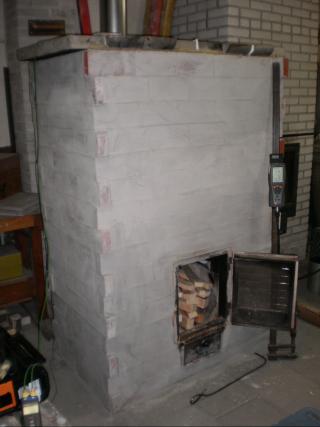 In the mean time the modified metalwork did arrive for the next and most important setup: the upscaled version! All dimension of that one are scaled up 1.7 times, except... the chimney. I know, it's not done, stick to the same surface area. But it do actually work, I am very happy with that. I've tried 3 different proportions of the second bell and the best seemed to be the third of the pictures: 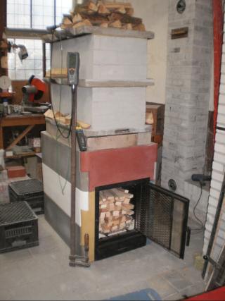 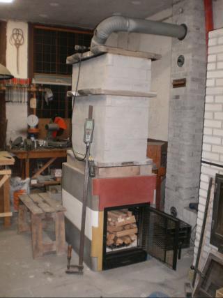 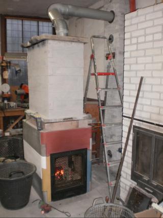 As you can see, a substantial part of the stove is made of refractory concrete. I do think the different colors are funny, these parts are leftovers from the makers of the commercial Bergkachel. The second I've been running with 24 pounds of oak and ash and I was very pleased with the results. See graphic: pberg0.home.xs4all.nl//pictures/versie7/test091011.gifAfter that test-run the side air supply was damaged and had to be replaced by a sturdier version. That one is holding out until now. Last week the Testo gas analyzer gave up the ghost and had to be sent to the service shop. Before that, some very interesting results were produced by the stove. 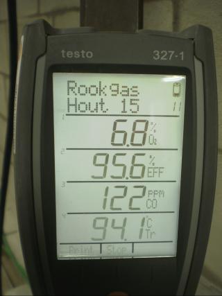 This week the Testo is expected to return, so I will be able to do some more tinkering with the air supply and proportions of the syphon. In due time, I will make a drawing available in SketchUp format with all the right dimensions and findings so far. |
|
|
|
Post by swizzlenutz on Nov 2, 2009 17:00:06 GMT -8
Peterberg, Do you build stoves for a living? If not you should, you do amazing work. If I was to decide to make a stove like yours I'd expect to be paying a decent amount for the blueprints. I think you should write a book on how to build the Peterberg's Bell Stove. Keep up the excellent work and thanx for sharing. Swizzle
|
|
|
|
Post by peterberg on Nov 4, 2009 13:23:54 GMT -8
Swizzle, no, I don't build stoves for a living. Tried it, end of the eighties, start of the nineties. I wasn't able to make a living out of that at the time so I gave it up. I am repairing rowing boats since 1997. And doing stove design and development in my spare time since 2002, just for fun.
Thank you for your kind words, I do like fan mail. This one I'll surround it with a nice frame and I'll give it a prominent place above my bed for sure.
|
|
|
|
Post by swizzlenutz on Nov 4, 2009 14:58:31 GMT -8
Well if I knew you were going to frame it I would have drew you a pretty picture to go with it. lol Maybe a Phoenix rising out of a rocket stove. Swizzle
|
|
|
|
Post by peterberg on Nov 15, 2009 13:40:14 GMT -8
Today, another test run has been performed. Air intake has been altered slightly, starting up problems has finally been overcome.
In fact, the firebox is loaded up to the edge of throat, with some kindling on top. As close to the syphon as possible. The kindling is lit and the regular air inlet closed and the loading door open for as much as about half system size. After about 10 to 15 minutes the syphon is warming up sufficiently, the rocket roar is starting to be very audible. The door is closed at that point, air inlet open slightly, something like a quarter system size.
The performance of the stove has been impeccably after that.
Moreover, refilling has been problematic up till now because shortly after that the CO would rise to a high peak, sometimes beyond the capacity of the Testo. Today's run was very successful in the sense that now the CO will rise slightly after refill. In 2 minutes or less the CO will go down again, sharply. To a level of less than 100 ppm, O2 level down to 7.8% at the same time. And only water vapor to be seen from the top of the chimney.
I'd call the results very good for this run. I am very happy, the thing is stable at last! A year ago I've said "I've got a dragon by its tail" and now I finally know the size of the dragon!
|
|
|
|
Post by canyon on Nov 17, 2009 10:45:44 GMT -8
Congratulations! I'm now looking forward to you petting the dragon and getting it to spit fire on demand!  |
|
|
|
Post by peterberg on Dec 6, 2009 9:07:31 GMT -8
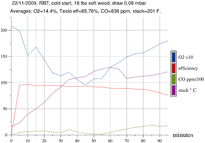 Last month I've spent some time in order to fine-tune the rocket/bell. Mainly to be able to get it started without heating up the stack with a torch. So far it's going remarkably well. I've prepared graphics of four test runs, to illustrate the results. 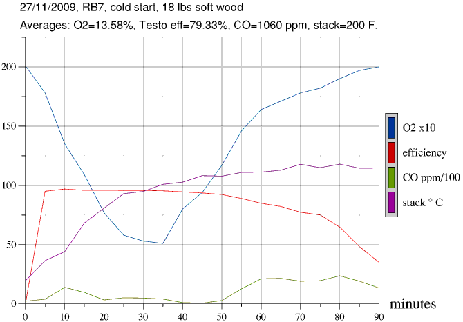 Note the similarities in the graphics, mainly in the CO line. There is always a small bump in the beginning, then a fairly extensive valley and a bigger bump at the end. The differences in O2 and stack temp are caused by fiddling with the air intake. In particular, the ratio between under air, front air and side air. The hotter the thing gets the more the emphasis will be on the side air. 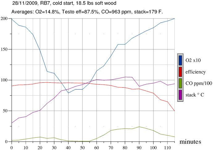 The fourth graph do show a sharp peak of carbon monoxide in the startup phase with an oxygen level less than 5%. In this particular case the side-air intake wasn't large enough. As a result, the siphon couldn't get sufficient air while the temperature was high enough. The interval of the graph is 5 minutes, while the peak actually lasted much shorter, something in the order of 2 minutes. It went down really as sharp as it went up. The conclusion seems to be: the oxygen level has to stay above 5%. When it's getting lower the likelihood of significant CO peaks are higher. 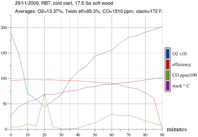 This fact do limit the maximum efficiency. Two factors play a role in here: the amount of air that need to be heated and the temperature that's discharged through the chimney. It seems to be better that the oxygen is higher than 5%, and during the top of the burn at least 140 degrees Fahrenheit to the chimney is needed. This results in a maximum yield of 97%, according to the Testo equipment. Some more and the fire behavior is getting unpredictable. Above each graph are the averages of that combustion run. Based on the graphs it's clear that it is not needed necessarily to have a low CO level in order to achieve high efficiencies. Of course, the quality of the combustion is better at a low CO level. After a cold start with outside temperatures below 50 F., a lot of water vapor's escaping the chimney which simply do resolve within five feet. Lighting the thing is always the same: stacking the wood to the edge of the siphon and on top of that a small fire of which the flames instantly disappearing into the siphon. In that way, it warms up quickly with an average value of 900 F. in 12 minutes. Opening the door at the height of the burn is not a good idea. As the siphon is lower than the top of the door, part of the smoke will come into the room. At the moment I have no recent graphs of a testrun which has had a refill. This do provide a complete show with generally very low numbers of CO and O2. All the wood burns simultaneously, but large jumps in the different values remain absent. The thing will make a lot of noise, a kind of dull roar. The oxygen will go lower than the limit of 5% in about half of the instances. Without the major peaks in the carbon monoxide readings. The dangerous point is thus mainly during the cold start, as the side aeration and the syphon are not hot enough yet. The mantle of the experimental model will be quite hot after a refill. The double walled side has reached 230 F. at one occasion. At the front, about 4" above the steel door frame 275 F. during the same run. During such sessions the syphon will exit between 1560 and 1790 degrees Fahrenheit from inside the stove. What the temperature at the hottest spot will be I don't know, I don't have a sensor in there. That would also be futile, the sensors I'm using cannot bear more than 1830 degrees F. This article is translated from Dutch by google translate. After a lot of editing by me, I do hope the result will be readable English. |
|
|
|
Post by Donkey on Dec 6, 2009 11:50:55 GMT -8
Peter, I've been reading up on bell stoves over at Kuznetsov's site.. Something he talks about is reducing the amount of "ballast gas" (cold, unusable air) in the fire. He talks about leaving a seam at the bottom of the firebox for colder air to pass directly into the bells, bypassing the flame-path and NOT cooling the fire. This colder air would never rise in the system to cool things off and would essentially exit directly out the chimney, bypassing the bells, est. He's coming from a masonry stove background, so his fire boxes are designed as such. I wonder if this idea could be used in some way with rocket stoves. Maybe a small opening at the base of the heat riser (rocket siphon you've been calling it) or on your design, below the riser somewhere down in the firebox. Looking at your images, I see a seam just about where I'm thinking..  Come to think of it, I don't see mortar at that seam. Are you already doing this?? |
|
|
|
Post by peterberg on Dec 6, 2009 13:09:00 GMT -8
Looking at your images, I see a seam just about where I'm thinking.. Come to think of it, I don't see mortar at that seam. Are you already doing this?? Hi Donkey, Yes, this is one of the configurations I've tested. The crevice you mention was stuffed with rockwool later on. To be honest, I've been using this in different forms. A horizontal seam under the opening, vertical left and right in the corners behind the tubing and at the bottom of the heat riser. For the last option, see my post from the 19th of May, at the top of this page. At the right side of the drawing there is a small block of text in Dutch which translates: "small leak in the shape of a crevice plus minus 3 mm". The 3 mm is about 1/8". In general, I wasn't able to detect a difference whether the "dry joint" in whichever form was open or closed. In terms of efficiency, that is. However, there is an effect, although predictable. Because the bell is all around the heat riser, heat is leaking away via this shortcut, and reaching the exit earlier. In this way, the stack is heated up faster. This effect is noticeable with all the configurations I've tested. In one single attempt, I've left the heat riser out altogether. The thing still worked, with the efficiency significantly less and the stack temp rising fast. At the moment I'm using another, simple technique to heat up the riser first described in my post of Nov. 15th. Doing away with all crevices, rauchslits and bypasses in one go. Even heating up the chimney once in a while with a torch or a paint stripper isn't necessary anymore. Conclusion: the open joint theory to lead cooler gasses away doesn't do what it should do. That counts for all my setups. As an aside: Alex Chernov, who's building bell systems in Canada, isn't convinced of the plausibility of this theory either. |
|


